
Executive Summary
Thermal-gradient deviation around a wafer chuck cooling-channel seal should be treated as a coupled system condition, not automatic proof of seal-material failure. A nonuniform thermal map may be associated with differential expansion, contact-pressure redistribution, cooling-channel flow behavior, contamination, chuck deformation or measurement bias. The direction and magnitude depend on the actual chuck geometry, coolant, pressure and flow conditions, assembly state, thermal load and measurement method.
A thermal map alone does not prove a leak, channel restriction or seal defect. The same local temperature difference can be produced by a physical gradient, a change in thermal contact, a sensor-placement effect or a data-processing choice. This article provides a general engineering framework for defining the boundary, preserving evidence, separating mechanisms and selecting validation methods. The actual chuck, seal, coolant and operating conditions must be confirmed before a corrective action or qualification claim is made.
Cooling-Channel Seal Boundary and Thermal-Gradient Sources
The relevant boundary may include the chuck body, cooling channel, seal groove or seat, mating surface, coolant path, nearby thermal interfaces and external hardware. The seal is one part of this boundary. A temperature deviation near the seal does not identify whether heat entered through the chuck body, was removed unevenly by the channel, was altered by contact conditions or was measured differently at different locations.
Possible sources include an uneven thermal path through the chuck body, routing or resistance differences in the channel, a local hot or cold region at the seal seat, start-up and cool-down transitions, repeated thermal cycling, mating-surface deformation and adjacent hardware. These are conditional engineering categories, not confirmed properties of a particular wafer chuck. The first useful question is whether the observed map is repeatable under a documented state and whether its location aligns with the seal boundary.
The seal line should be inspected together with the nearby channel interface. A seal may experience a local change in compression when the surrounding materials expand differently, but a similar symptom can arise when a mating surface is uneven, a clamp or fastener load is not uniform, or a sensor is positioned closer to one thermal path than another. Boundary definition prevents a thermal observation from being collapsed into a material diagnosis.
Table 1. Thermal-Gradient Sources and Cooling-Channel Seal Boundary Effects
| Possible source or location | Local thermal or mechanical condition | Possible seal-boundary consequence | Evidence to check | Limitation |
| Uneven chuck thermal path | Different heat-transfer path through body | Local expansion or contact change | Thermal map and chuck design review | Does not identify seal response alone |
| Channel routing or resistance | Nonuniform heat removal | Different seal-seat temperature | Flow evidence and channel records | Actual routing must be confirmed |
| Seal-seat hot or cold region | Local surface condition differs | Compression redistribution | Surface map and interface inspection | A map needs validated spatial resolution |
| Start-up or cool-down | Transient thermal state | Temporary contact-pressure change | Time history and repeat cycles | Single snapshot is limited |
| Thermal cycling | Repeated expansion and contraction | Recovery or stress-relaxation concern | Cycle history and seal condition | No life claim without defined testing |
| Mating-surface deformation | Flatness, alignment or local stiffness effect | Uneven contact or gap risk | Surface and alignment evidence | No deformation value is assumed |
| Adjacent hardware | External heat source or sink | Local boundary-condition shift | Hardware layout and insulation review | Effect may not originate at the seal |
| Measurement location | Sensor sees a different thermal path | Apparent rather than physical deviation | Sensor placement and calibration | Sensor error cannot be inferred from shape alone |
How Thermal-Gradient Deviation Can Change Seal-Line Conditions
Temperature differences across a seal boundary can change the relative dimensions and stiffness of the seal, chuck body and mating surface. Depending on the materials, geometry and temperature history, the result may be a change in compression, recovery, contact pressure or local gap. Thermal exposure may also influence stress relaxation or compression set. These mechanisms must remain conditional because the same temperature change can produce different responses in different materials and geometries.
A local hot or cold region may redistribute contact pressure rather than create a uniform change around the entire perimeter. A corner, transition or channel-adjacent land may respond differently from a broad flat region. If the contact path is already affected by residue, particles, misalignment or surface damage, a thermal change may expose or amplify an existing condition without being its original cause. The seal and its seat should therefore be inspected for location-specific evidence.
A measured thermal deviation can also be a consequence rather than a cause. A local gap, altered contact, contamination layer or deformed mating surface may change heat transfer and create a temperature signature near the seal. Likewise, a cooling-channel flow imbalance can change the map while the seal remains intact. The investigation should ask whether the thermal signature precedes the sealing symptom, follows it, or changes only after measurement setup or maintenance.
Table 2. Thermal-Gradient Signatures and Alternative Mechanisms
| Observation or symptom | Thermal-gradient possibility | Alternative mechanism to separate | Verification approach | Limitation |
| Local temperature deviation near perimeter | Uneven heat removal or body path | Sensor placement or calibration bias | Repeat map with documented setup | Map does not prove leakage |
| Change after start-up | Transient expansion or flow state | Sensor response time or stabilization | Time-resolved repeat check | No universal stabilization time |
| Leak after thermal cycling | Compression or recovery change | Assembly variation or surface damage | Thermal-cycle boundary test | One cycle set is not service life |
| Visible seal deformation | Thermal expansion or material response | Installation, extrusion or compression set | Seal and geometry comparison | Appearance alone is not causal |
| Nonuniformity after maintenance | Changed seating or thermal contact | Sensor relocation or cleaning residue | Before/after setup audit | Maintenance records may be incomplete |
| Map changes with sensor position | Spatial-resolution or contact effect | Instrument bias or emissivity assumption | Cross-check sensor method | Measurement method must be documented |
| Local hot or cold spot at seat | Channel path or adjacent hardware | Surface condition or external boundary | Design and boundary-condition review | Origin requires system evidence |
| Pressure drift with thermal change | Seal contact or fluid-property interaction | Channel restriction or instrumentation | Separate leak and flow checks | Correlation is not root cause |
Cooling-Channel Flow, Thermal Cycling and Measurement Effects
The observed gradient depends on the coolant state, flow path, pressure history, heat load, start-up and cool-down behavior, nearby surfaces and the measurement method. A channel may remove heat unevenly because of routing, local resistance, a restriction, trapped gas or a flow-distribution condition. These possibilities require actual channel and operating evidence. They must not be replaced with an invented flow rate, pressure drop or thermal value.
Thermal cycling matters because the seal, chuck body and mating hardware may not respond at the same rate. During a transition, a seal can see a short-lived compression change even when the steady-state map looks uniform. Repeated transitions may also expose recovery loss, stress relaxation or a maintenance weakness. A single steady-state map cannot establish the behavior during every ramp, dwell or cool-down condition.
Measurement practice is part of the thermal boundary. Sensor placement, calibration, response time, spatial resolution, surface emissivity assumptions and data processing can change the apparent shape of a map. Infrared measurements, contact sensors and embedded sensors each have different observation limits. The appropriate method depends on the surface and access. A credible report states how the map was obtained, what was measured, what was interpolated and which regions were not observed.
Table 3. Inspection and Validation Guide for Wafer Chuck Cooling-Channel Seal Concerns
| Check or test | Objective | Key variable or evidence | What it may indicate | Limitation |
| Pre-disassembly thermal record | Preserve original state | Map, timing, equipment condition | Repeatable symptom location | Does not identify mechanism |
| Sensor placement review | Check spatial and setup bias | Position, contact and orientation | Apparent map distortion | Needs known-good reference |
| Calibration and repeatability | Assess measurement confidence | Calibration status and repeat runs | Measurement uncertainty | Accuracy alone does not prove uniformity |
| Cooling-channel flow review | Assess distribution or restriction | Available flow and pressure evidence | Possible heat-removal imbalance | Instrumentation may not see all paths |
| Thermal-cycle observation | Observe transient response | Ramp, dwell and cool-down history | Cycle-dependent contact change | Requires defined cycle condition |
| Seal and seat inspection | Find local boundary evidence | Damage, residue, seating and recovery | Contact or material response | Physical evidence may be altered by cleaning |
| Material exposure screening | Assess conditional material response | Actual fluid and thermal sequence | Possible expansion or property change | Not assembled-boundary proof |
| Assembled leak verification | Check boundary at stated state | Thermal and pressure test condition | Leak behavior under test | Not lifetime or full-map proof |
| Post-maintenance cross-check | Confirm restored setup | Installation, map and boundary result | Change after service | Cannot generalize beyond setup |
Seal Material, Geometry and Chuck-Design Considerations
There is no universal best seal material for every wafer chuck cooling-channel design. Selection should connect the confirmed coolant and cleaning environment with compound compatibility, seal cross-section, groove or seat geometry, compression, mating-surface condition, chuck stiffness, thermal expansion, channel routing and maintenance. Chemical compatibility is important where applicable, but it does not by itself establish thermal-cycle recovery, compression retention or assembled-boundary reliability.
Geometry determines how thermal expansion is translated into contact pressure and gap. Cross-section, squeeze, retaining features, channel proximity, corner transitions and surface finish should be reviewed together. A seal near a stiff metal land may respond differently from one beside a compliant or thermally isolated region. Clamping or fastening can also redistribute load. These are design questions requiring actual drawings and assembly data, not universal rules.
A robust review separates material screening from assembly verification. Material exposure can examine response under selected coolant, cleaning and thermal conditions. Compression or recovery measurements can examine a component-level change. Thermal maps can describe temperature distribution. Leak or pressure-decay tests can assess an assembled boundary under defined conditions. None of these tests should be presented as a substitute for the others or as proof of service life without representative evidence.
Inspection, Root-Cause Separation and Validation Testing
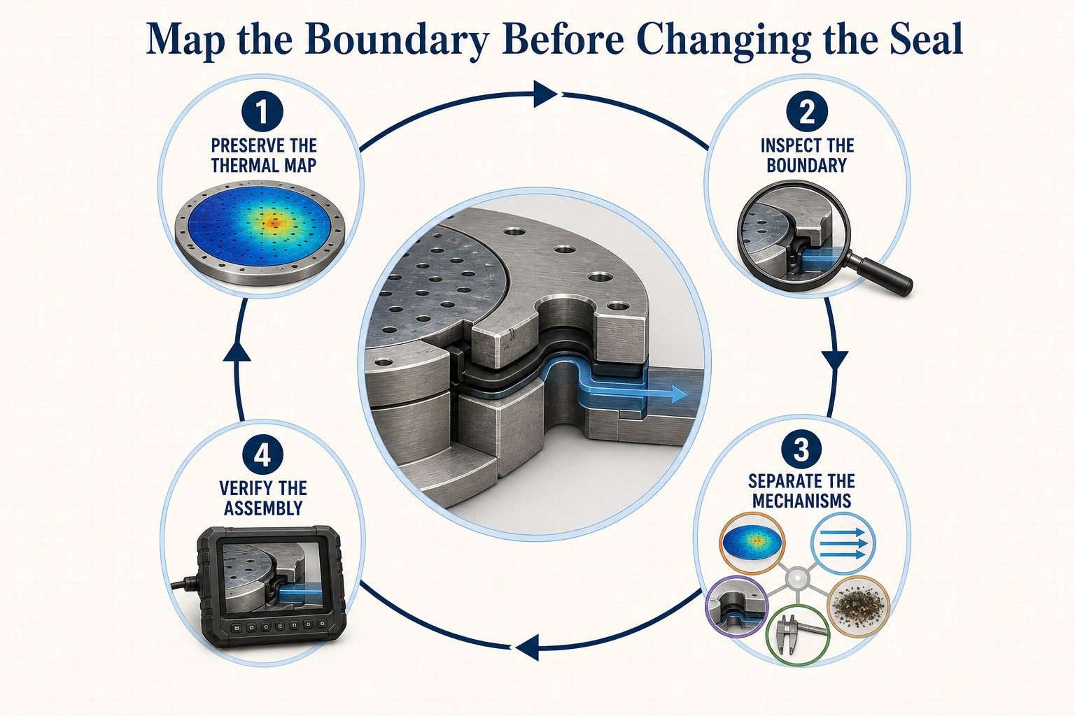
Begin by recording the thermal and sealing symptom before cleaning, disassembly or sensor relocation changes the evidence. Document the map location, test state, timing, sensor type, measurement setup and any maintenance activity. Record chuck, channel, seal and assembly information when available. Preserve photographs, used components and residue where appropriate. A result should be classified as observed, suspected, confirmed, inconclusive or not evaluated.
Inspect the seal, groove or seat, mating surface, channel interfaces and contamination condition. Review alignment, seating marks, compression evidence and surface condition. Check cooling-channel routing, possible restrictions and trapped-gas concerns without assuming that a blockage exists. Compare used and unused or known-good components only when the comparison is appropriate. Review material response, dimensional change, hardness or compression behavior only with defined conditions.
Repeat or cross-check the thermal measurement with a documented and calibrated method where feasible. The objective is not to force two instruments to produce the same map, but to understand differences caused by placement, surface response, resolution or processing. Then verify the assembled boundary under relevant thermal and pressure conditions, clearly stating the limitation of each test. A room-temperature leak check does not establish thermal-cycle performance; a thermal map does not prove a leak; a material test does not prove assembled sealing.
The investigation should close the evidence loop by comparing the thermal symptom with seal location, channel behavior, assembly state and measurement uncertainty. If the evidence remains ambiguous, the correct conclusion is inconclusive or not evaluated, not a confident material recommendation. This prevents a seal change from masking a channel, chuck, contamination or instrumentation issue.
Design, Maintenance and Process Controls
Controls should match the mechanism being addressed. For thermal nonuniformity, review thermal-map repeatability, sensor placement, calibration, cold spots, hot spots and cooling-channel distribution. For material response, review coolant and cleaning compatibility and representative exposure. For compression loss, review geometry, dwell, thermal history and recovery evidence. For contamination, review cleaning, handling and contact-surface control. For assembly, review alignment, seating and post-maintenance verification.
Maintenance records should link seal orientation, replacement status, cleaning and drying, assembly condition, channel state, thermal-map setup and boundary-test results. A seal that looks acceptable may still have recovery loss, hidden distortion, residue or an incorrect seating condition. Reuse decisions should follow equipment-specific criteria and evidence rather than appearance alone. If the actual acceptance limit or replacement interval is not supplied, the article can recommend a review but cannot assign a universal threshold.
Where a design change is considered, define the problem before changing the channel, seal or chuck. A change intended to reduce a thermal gradient may not correct a measurement bias. A new seal compound may not correct an uneven mating surface. A flow adjustment may not correct a compression difference. The most efficient path is to map the boundary, preserve evidence and run tests that separate thermal, mechanical, fluid, contamination and measurement effects.
FMEA Risk Analysis: Thermal-Gradient Deviation at Cooling-Channel Seals
The following qualitative FMEA is an engineering screening aid, not field statistics, a product rating or a confirmed failure analysis. It contains no assumed probability, severity, RPN, temperature, pressure, leak-rate, wafer-result or service-life claim. Every row requires confirmation against the actual chuck, channel, seal, assembly and measurement history.
Table 4. Qualitative FMEA for Thermal-Gradient Deviation at Cooling-Channel Seals
| Failure Mode | Cause | Local Effect | System Effect | Detection Method | Control Action |
| Uneven thermal condition near seat | Body path or channel distribution difference | Local expansion or contact change | Thermal map deviation or leakage sensitivity | Map and boundary inspection | Review thermal path and assembly |
| Differential expansion across boundary | Materials respond differently to heat | Compression redistribution | Cycle-dependent boundary behavior | Thermal-cycle and contact review | Match geometry and material evidence |
| Compression loss after cycling | Dwell, cycling or stress relaxation | Reduced recovery | Lower contact pressure | Recovery and assembled test | Define representative conditions |
| Local gap opening or extrusion | Changed geometry, gap or load | Edge displacement or nibbling | Localized leakage risk | Geometry and seal inspection | Correct verified gap or load path |
| Channel flow maldistribution | Routing, resistance or restriction | Uneven heat removal | False seal diagnosis or local hot/cold region | Flow and pressure evidence | Review distribution and restrictions |
| Trapped gas or poor fluid contact | Incomplete filling or path condition | Local heat-transfer change | Transient or repeatability issue | Channel-state review | Control filling and operating sequence |
| Chuck-body deformation | Thermal expansion, stiffness or load | Changed seat or mating surface | Uneven contact and map shift | Flatness and alignment evidence | Review body and interface design |
| Particle or residue standoff | Cleaning, handling or process contamination | Local contact interruption | Leak or thermal-contact artifact | Interface microscopy and residue review | Control cleanliness and reassembly |
| Post-maintenance uneven seating | Misalignment, twist or incomplete seating | Local compression difference | Repeat symptom after service | Seating and installation record | Controlled assembly and verification |
| Sensor placement bias | Position, contact or emissivity assumption | Apparent gradient | Wrong corrective action | Repeat map and setup audit | Standardize measurement method |
| Calibration or processing bias | Drift, response or interpolation choice | Map offset or smoothing artifact | Uncertain thermal conclusion | Calibration and raw-data review | Document calibration and processing |
| External thermal boundary effect | Adjacent hardware, radiation or insulation | Local heat input or removal | Nonuniform map near seal | Hardware and environment review | Control boundary conditions |
| Chemical material response | Coolant or cleaner interaction | Expansion, hardening or softening | Compression or friction shift | Exposure and material review | Confirm compatibility under conditions |
| Thermal map treated as root cause | Observation-only diagnosis | Wrong mechanism assigned | Repeated failure or wasted change | Failure-analysis review | Separate observation from inference |
| Component test treated as system proof | Test boundary not stated | Overextended conclusion | Unverified service claim | Scope and limitation review | Link component and assembly tests |
Conclusion
Thermal-gradient deviation at a wafer chuck cooling-channel seal is best investigated as a coupled thermal, mechanical, fluid and measurement condition. A nonuniform map can be consistent with differential expansion, compression redistribution, channel behavior, contamination, chuck deformation or sensor bias, but it does not by itself prove seal-material failure or establish the cause of a leak.
A defensible corrective action begins with the actual chuck and channel design, coolant information, thermal map, flow and pressure conditions, seal details, assembly history and measurement method. Separate the physical map from measurement uncertainty, component response from assembled-boundary performance and a possible mechanism from a confirmed diagnosis. Only then should the team decide whether to review the seal material, compression and geometry, cooling-channel flow, chuck structure, contamination controls or the measurement system.
FAQ
Q:Why can a wafer chuck cooling-channel seal experience a thermal gradient?
A:A gradient may arise from the chuck thermal path, cooling-channel routing or resistance, local boundary conditions, thermal cycling, nearby hardware or the measurement setup. The actual source depends on the confirmed design and operating state. A local map deviation should therefore be investigated rather than assigned to the seal automatically.
Q:Does a nonuniform thermal map prove that the seal has failed?
A:No. A map describes a measured temperature condition; it does not by itself establish leakage, material failure or channel blockage. Sensor placement, calibration, flow behavior, chuck deformation, contamination and contact conditions may produce overlapping signatures.
Q:How can thermal-gradient deviation change seal compression?
A:Different expansion or stiffness responses may redistribute contact pressure, change recovery or create a local gap. The direction and magnitude depend on material, geometry, temperature history and assembly load. Component and assembled tests should be kept separate.
Q:Can cooling-channel flow imbalance resemble a seal problem?
A:Yes. Uneven heat removal, a restriction, routing differences or an incomplete fluid state may create local temperature variation without a seal defect. Flow and pressure evidence should be reviewed alongside seal and boundary evidence.
Q:How should sensor placement and measurement error be evaluated?
A:Document sensor type, location, contact or optical assumptions, calibration, response time, spatial resolution and data processing. Repeat or cross-check the map with a documented method where feasible. Differences between methods are evidence to analyze, not proof that one map is correct.
Q:What should be inspected before replacing a wafer chuck cooling-channel seal?
A:Record the original thermal and sealing symptom first. Inspect the seal, groove or seat, mating surface, channel interfaces, contamination, alignment and seating. Review maintenance history and measurement setup before choosing a replacement material or redesign.
Q:Which tests can verify a cooling-channel seal under thermal cycling?
A:A representative plan may combine thermal mapping, component exposure or compression review and assembled-boundary leak verification under defined thermal and pressure conditions. Each test has a different purpose and limitation. No single test establishes full-life performance without supporting evidence.
Q:How can particles or contamination affect the thermal and sealing boundary?
A:Particles or residues may create local standoff, scratches, wetting changes or altered thermal contact. They can coexist with a real gradient or create an apparent one. Preserve the evidence, inspect the interface and separate particle, chemical, thermal and assembly findings.
Post time: Sep-12-2026