
Executive Summary
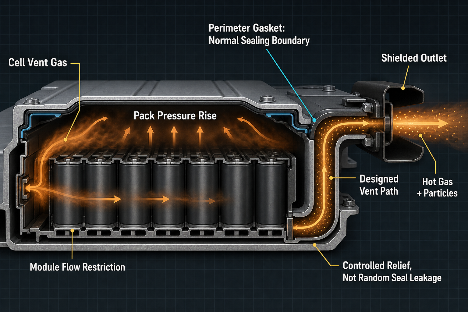
Thermal-runaway pressure relief in battery-pack sealing is a boundary-management problem. Cell venting, module gas transport and pack-level discharge happen in different spaces, with different restrictions and time scales. A cell may vent successfully while the module or pack still accumulates hot gas because the downstream path, free volume, vent area and enclosure stiffness control pressure redistribution.
The pack gasket is normally not the emergency pressure-relief device. Its routine function is water and dust exclusion, environmental isolation, sealing-force retention and structural joint integrity. If gas leaves through gasket extrusion, cover lift, seal blowout or joint rupture, the event may lower pressure, but it is not controlled relief unless activation, direction, flow capacity and downstream exposure were deliberately designed and validated.
A robust design must separate normal sealing, pressure equalization, thermal-event relief, flame and particle management, containment and post-event integrity. A battery-pack sealing system should preserve environmental protection during normal operation while directing thermal-runaway gases through a deliberately designed and validated relief path.
Pressure Boundaries from Cell Vent to Pack Enclosure
A battery pack contains layered pressure boundaries: the cell enclosure and cell vent, module covers and channels, the pack housing, upper and lower covers, perimeter gaskets, cable and busbar penetrations, coolant interfaces, service disconnect openings, pressure-equalization membranes, emergency vents and drainage features. These boundaries do not perform the same job. The cell vent releases internal cell pressure; the module architecture shapes the jet and restriction; the pack enclosure determines whether gas is contained, redirected or discharged.
Cell pressure must not be confused with pack pressure. After vent activation, gas may enter busbar cavities, compression-pad gaps, module voids or blocked regions before reaching the pack free volume. Brackets, cooling plates, harness routing and crossmembers can produce asymmetric propagation and local pressure concentration. A pressure sensor placed near a vent, in a stagnant corner or in the central cavity may record different histories from the same event.
Sealing architecture changes the response. Molded perimeter gaskets rely on controlled squeeze, liquid-applied sealants depend on bead geometry and cure, foam seals deform under low load, and metal flanges determine cover lift. Connectors, service openings and coolant ports may become secondary paths if their compression or interface design differs from the cover joint. Normal breathing membranes should not be assumed to pass hot, particle-laden runaway gas.
The design boundary should therefore be written in layers: normal sealing prevents water, dust and contaminants; pressure equalization manages slow breathing; emergency relief handles abnormal hot-gas discharge; containment limits flame, particles and vapor migration; post-event integrity determines whether the pack can be handled, inspected or replaced safely.
Table I. Battery-Pack Pressure Boundaries and Sealing Functions
|
Boundary |
Component |
Normal role |
Event concern |
Check focus |
Limit |
| Cell | Cell can, vent | Containment | Gas source | Cell vent data | Not pack relief |
| Module | Cover, channel | Routing | Restriction | Gas-flow test | Not full pack |
| Pack seal | Cover, gasket | Water/dust seal | Blowout | Leak, squeeze | Not emergency vent |
| Equalization | Membrane | Breathing | Hot-flow overload | Pressure cycling | Not runaway proof |
| Emergency relief | Panel, duct | Directed relief | Flame, particles | Vent test | Needs validation |
| Containment | Shield, housing | Exposure control | Unsafe migration | Post-event review | Not just sealing |
Gas Generation, Pressure Accumulation and Controlled Venting
Thermal runaway may start from internal short circuit, overcharge, external heating, separator failure or mechanical abuse. Once heat generation exceeds heat rejection, electrolyte vaporization and decomposition of electrodes, binder and other materials generate hot gas and vapor. The relevant pressure is not governed by total gas quantity alone. Gas-generation rate, temperature, density, free volume, flow resistance, opening area and vent timing jointly determine pressure rise.
Cell vent activation is only a transfer point. A cell may discharge into a module cavity, but module walls, pads, covers, busbars and harnesses can restrict the jet. Sequential cell failures may create overlapping flow pulses and short pressure peaks that are not represented by a single-cell test. Hot gas can also soften nearby seals, change compression distribution, attack surfaces and deposit residues that alter later leakage paths.
Controlled venting is different from random leakage. A designed vent defines activation behavior, flow capacity, discharge direction, thermal shielding, flame path and particle migration. Burst panels, frangible features, labyrinths, directional ducts, shields and deflectors can be engineered for these objectives. Gasket bypass, cover lift, joint rupture or housing cracking may release gas, but their start pressure and direction are uncertain unless they are part of a validated relief concept.
Vent-path design must evaluate transient flow, not merely gas volume. Long passages, sharp turns, small sections, membranes, screens and particle retainers increase pressure drop. Multiple vents may add redundancy, but unequal resistance can shift most flow to one path. Sealant, foam, dust, ice, condensate, debris or displaced harnesses can obstruct relief. Discharge must avoid occupants, service zones, high-voltage connectors, coolant lines, flammable materials and neighboring cells where possible.
Table II. Thermal-Runaway Pressure-Relief and Seal-Risk Matrix
|
Factor |
Primary |
Secondary |
Failure mode |
Measurement |
Limit |
| Small vent | High pressure | Cover load | Deformation | Pressure, flow | Case specific |
| Wrong direction | Unsafe jet | Exposure | Thermal damage | Video, temp | Layout dependent |
| Blocked channel | Delayed relief | Local peak | Joint rupture | Flow check | May be hidden |
| Weak squeeze | Daily leak | Water ingress | Seal bypass | Compression map | Not relief proof |
| Hot jet | Seal softening | Residue | Gasket blowout | Thermal evidence | Not cause alone |
| Debris | Restriction | Corrosion | Vent blockage | Inspection | Changes over time |
Seal Response under Hot Gas, Pressure and Chemical Exposure
Battery-pack seals can soften, decompose, char, swell, shrink, extrude, blow out, tear, lose adhesion, lose compression force or generate residue during a thermal event. Data-sheet temperature limits are not sufficient because hot-gas impingement produces non-uniform heating, erosion, solvent exposure and pressure loading unlike uniform oven aging. Local jet exposure can damage one part of a gasket while remote regions remain visually unchanged.
Cover deformation and preload loss can change the contact band before the seal material itself fails. A softened gasket near a clearance may extrude into a gap, opening an unintended gas path or blocking a designed vent channel if the relief path and sealing bead are poorly separated. Adhesive gaskets and liquid sealants may fail by bond loss, cohesive tearing or charred residue rather than simple leakage.
Electrolyte vapor, solvent decomposition products, coolant and cleaning residues may change hardness, tackiness, swelling or surface integrity. Charring or powdering does not prove the seal caused the event; it only shows exposure. An unseated gasket may indicate design intent, pressure overload, assembly error or teardown damage. Post-event seal morphology must be read together with pressure trace, temperature record, gas-flow direction, housing deformation and material analysis.
Material selection must therefore combine normal service and abnormal exposure. EPDM, FKM, silicone, FVMQ, HNBR, NBR, foam seals, liquid sealants, adhesive gaskets and conductive gaskets each have different limits in compression set, vapor exposure, outgassing, electrical compatibility, particle generation and reworkability. No elastomer is universally best; high-temperature or flame-resistant behavior does not make a gasket an emergency vent.
Normal Sealing, Equalization and Multi-Physics Trade-Offs
Normal sealing and emergency relief must remain separate design functions. During service, temperature change, altitude variation and pressure cycling create breathing of the enclosure. Pressure-equalization membranes may protect the gasket from slow differential pressure while resisting water and dust, but this does not mean they can handle hot, fast, chemically aggressive and particle-laden runaway gas.
Water management complicates vent design. Drain paths, water traps and membrane locations may interact with emergency discharge, while condensate, mud, dust, salt or ice can restrict openings. Under-compressed seals create daily ingress risk; over-compressed seals raise assembly stress, accelerate compression set and make service more difficult. A water-ingress test proves environmental sealing under that test condition, not thermal-runaway relief.
Thermal, mechanical and chemical loads act together. Housing expansion, module swelling, vibration, shock, crash deformation and bolt-preload change all affect compression distribution. Pressure pulses may cause gasket micro-slip. Thermal gradients can make hot-side seal zones respond differently from remote regions. Crash damage can also block a designed vent path or create a new leakage route. The design must consider normal operation, service, collision, thermal cycling and post-event state as different boundary conditions.
Application-Specific Risk Patterns
Passenger electric vehicles emphasize occupant protection, underbody discharge, waterproofing and crash damage. The pack is often a large structural enclosure with perimeter gaskets, cooling interfaces and service openings. The preferred relief concept normally directs hot gas away from the cabin and critical high-voltage zones. Verification should examine discharge direction, post-impact deformation and whether adjacent structures block or redirect the vent path.
Commercial and off-highway vehicles add vibration, shock, mud, dust and frequent service exposure. Their vent channels must remain open despite debris and maintenance residue. Stationary energy-storage systems focus on cabinet-level propagation, personnel exposure and sequential module events, where module isolation and directional cabinet discharge may matter as much as pack sealing. Marine and high-humidity packs add corrosion, condensation and pressure-equalization stress.
Battery modules, swap systems, high-power charging equipment and small portable enclosures each shift the interpretation. Repeated handling can degrade connectors, gaskets and vent interfaces. Small enclosures have little free volume, so minor restrictions can create rapid pressure rise. No single discharge direction, seal rating or validation method applies across applications; the boundary definition must follow the enclosure configuration and exposure zone.
Inspection, Testing and Evidence Classification
Validation should not collapse different functions into one test. Leak, pressure-decay, helium, water-ingress and dust-ingress tests assess environmental sealing. Thermal cycling, altitude cycling, vibration, shock, housing deformation measurement and gasket compression mapping show how the boundary changes before abuse. These tests are necessary, but they do not prove hot-gas discharge, flame direction or particle control.
Cell vent characterization, module gas-flow testing, pack pressure measurement and pressure-rise-rate measurement connect the gas source to enclosure response. Empty-pack pressure tests help quantify resistance, but they cannot reproduce multi-cell heat release, vapor chemistry, flame, particles or structural heating. Thermal-runaway and controlled vent-path tests should record pressure, temperature, gas direction, vent state, deformation, flame or particle observation, residual pressure and gasket morphology.
Post-event analysis should classify evidence as observed, suspected, confirmed, inconclusive or not evaluated. Seal failure, vent-path failure, housing failure, cell-vent failure, adjacent-component failure, secondary damage and handling damage must be separated. A charred seal, deformed cover or displaced gasket is not root cause by itself. Root-cause judgment requires video, pressure curves, temperature records, deformation maps, residue location, material condition and flow-path evidence.
Thermal-runaway testing involves hot gas, flammable mixtures and pressure hazards. It should be performed only by qualified laboratories with proper facilities and protection. The article should never be interpreted as an instruction to reproduce abuse testing in ordinary workplaces; the engineering goal is validated evidence, not uncontrolled demonstration.
Table III. Battery-Pack Sealing and Pressure-Relief Verification Guide
|
Test |
Objective |
Variable |
Detects |
Stage |
Limit |
| Leak test | Normal seal | Pressure decay | Joint leak | End-of-line | No hot gas |
| Water test | IP protection | Exposure | Water path | Design validation | No runaway data |
| Thermal cycling | Aging effect | Temperature | Compression drift | DV/PV | Slow event only |
| Module flow | Restriction | Flow path | Accumulation | Design validation | May lack flame |
| Pack pressure | Relief response | Sensor site | Pressure peak | Abuse test | Location sensitive |
| Post-event review | Damage evidence | Exposure map | Seal damage | Failure analysis | Not cause alone |
Process Control, Traceability and FMEA Risk Logic
Stable sealing cannot depend only on final waterproof testing. Incoming gasket inspection, compound traceability, dimensional checks, compression-height verification, groove cleanliness, housing flatness, bolt torque, assembly sequence, lubricant control and sealant application all affect the boundary. Vent channels, membranes, shields and drains must remain free from sealant, foam, harness interference, dust and service residue.
Material, gasket-section, housing, vent-part or assembly-process changes require requalification because they can alter compression set, volatile release, blockage risk and high-temperature response. Post-collision and post-event packs should not be released by appearance alone. Records should connect cell batch, module batch, gasket batch, vent components, assembly data and test history so field returns can be interpreted correctly.
FMEA must treat waterproofing, pressure relief and post-event integrity as separate risk groups. Designed relief differs from random leakage because it controls activation, capacity, direction and exposure. Unverified pressure, flow or vent behavior should remain an engineering hypothesis until test evidence confirms it. The RPN values below are illustrative engineering risk rankings, not field statistics or experimental results.
Table IV. Battery-Pack Thermal-Runaway Sealing FMEA
|
Failure mode |
Cause |
Local |
System |
Detection |
RPN |
Action |
| Blocked vent | Debris, sealant | Delayed relief | Pressure rise | Vent inspection | 210 | Protect path |
| Small vent | Low area | High pressure | Cover lift | Flow test | 196 | Resize relief |
| Wrong direction | Layout | Hot impingement | Unsafe exposure | Thermal video | 189 | Redirect jet |
| Seal blowout | Pressure, heat | Boundary loss | Random discharge | Pressure trace | 180 | Dedicated vent |
| Cover lift | Pressure peak | Contact loss | Leak, rupture | Deformation map | 175 | Stiffen or vent |
| Water ingress | Post-event damage | Corrosion | Service hazard | Ingress test | 144 | Replace parts |
| Unverified relief | Assumption | Unknown path | False claim | Validation audit | 200 | Test, document |
Conclusion
Thermal-runaway pressure relief is not a request to make the gasket weaker. It is a system design problem involving cell venting, module flow restriction, pack free volume, enclosure stiffness, directed relief, flame and particle management, adjacent-component protection and post-event integrity. The gasket should preserve normal environmental protection, not act as a random emergency vent.
Effective battery-pack design separates normal sealing, pressure equalization, thermal-event relief, containment and post-event assessment. Water-tightness tests, ordinary leak tests and single-cell runaway tests cannot replace one another. Final judgment must return to controlled venting, defined sealing boundaries, protected discharge direction, validated evidence and long-term safety reliability.
Engineering FAQ
Q:Is a battery-pack gasket intended to release thermal-runaway pressure?
A:Usually no. The gasket protects the pack from water, dust and environmental contamination while maintaining a sealing boundary. Thermal-runaway gas should be routed through a dedicated and validated relief path. Gasket leakage, extrusion or blowout is only an observed response unless the design defines and verifies that behavior.
Q:What is the difference between cell venting, module venting and pack-level venting?
A:Cell venting releases gas from the cell. Module venting describes movement through module spaces, barriers or channels. Pack-level venting is controlled discharge from the enclosure to a safer exterior direction. A cell vent may open while the module or pack still accumulates pressure because downstream resistance and vent location remain unresolved.
Q:Why can excessive enclosure sealing increase thermal-event risk?
A:Very strong sealing can raise pressure load on the housing, cover joint and fasteners if relief is insufficient. Weak sealing is not safer; it may cause water ingress and random hot-gas discharge. The correct approach is a robust normal seal plus a validated relief path.
Q:Can a pressure-equalization membrane handle thermal-runaway gases?
A:It should not be assumed. A normal membrane is intended for breathing caused by temperature or altitude change while resisting water and dust. Thermal-runaway gas may be hot, fast, chemically aggressive and particle-laden. Membrane use requires testing for flow capacity, thermal resistance, contamination tolerance and failure behavior.
Q:Why can a waterproof enclosure test not prove thermal-runaway safety?
A:A waterproof test verifies liquid-entry resistance under defined conditions. It does not reproduce hot gas, rapid pressure rise, flame, particles, electrolyte vapor, vent blockage or housing deformation. Conversely, a thermal-event test does not prove long-term immersion durability. Normal sealing and emergency relief require separate evidence.
Q:How should a battery pack be inspected after a thermal event?
A:Inspection should document vent state, housing deformation, gasket condition, fasteners, connectors, wiring, coolant interfaces, residue and pressure-temperature records. Photographs should include scale, orientation and exposure location. A pack should not be cleared by appearance alone; service decisions need testing and replacement criteria.
Post time: Sep-08-2026