
Executive Summary
AI server workloads can change faster than the liquid cooling system reaches a new steady state. When GPU activity rises, chip heat flux increases first; the cold plate, coolant, sensors, pump and valves respond on different time scales. The resulting risk is not limited to insufficient steady-state capacity. A delayed or poorly tuned control loop can also create local temperature rise, flow overshoot, actuator hunting or temperature oscillation.
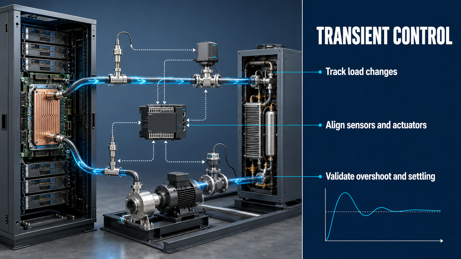
Transient thermal management is the coordinated control of coolant flow and temperature while the server heat load changes over time. A reliable direct liquid cooling system must therefore control pump speed, valve position, flow rate and supply temperature using time-aligned feedback from the chip, cold plate, supply line and return line. The objective is a stable response that protects the thermal envelope without creating unnecessary hydraulic or control disturbance.
The governing sequence is: workload increase -> heat-load increase -> chip temperature response -> sensor detection -> controller calculation -> pump or valve action -> coolant flow change -> temperature recovery. Each link has a delay, a limit and a failure mode. These properties must be measured rather than inferred from steady-state data.
Workload Transients and Thermal Response
A step load is an abrupt change in heat generation; a ramp load changes heat generation over a defined slope. The two inputs exercise different parts of a cooling control system. A step load exposes sensor and actuator delay, while a ramp load shows tracking error and whether the control loop follows the changing demand without persistent offset. Neither input should be represented by a universal GPU power curve unless the server, workload, instrumentation and test method are specified.
The chip package has a small thermal mass and can change temperature before the coolant temperature changes appreciably. The cold plate, coolant volume, piping and heat exchanger add different levels of thermal inertia. Chip temperature, cold-plate temperature, coolant supply temperature and coolant return temperature therefore do not move at the same time. A return-temperature sensor may confirm the event after the chip has experienced its maximum local thermal stress.
For an illustrative engineering example, a rapid positive heat-load change may first appear as a chip-temperature slope, followed by a delayed change in cold-plate temperature, then a supply or return temperature response. The exact timing depends on the coolant, flow rate, cold-plate construction, sensor location, filtering and system volume. The example is a response concept, not a performance claim for a particular server.
Table I: AI Workload Transient and Cooling Response Chain
|
Workload condition |
Heat-load change |
Expected coolant response |
Main control variable |
Potential thermal risk |
Recommended control action |
| Low to high step | Rapid positive change | Flow and temperature response must accelerate | Pump speed and flow command | Chip temperature overshoot | Use validated response with rate limits |
| High-load hold | Near-constant high load | Loop approaches a new steady state | Supply temperature setpoint | Persistent thermal offset | Verify steady tracking and sensor agreement |
| High to low step | Rapid negative change | Demand falls faster than actuator reset | Pump speed and valve position | Excessive flow or hunting | Coordinate ramp-down and minimum-flow logic |
| Repeated cycling | Alternating positive and negative changes | Loop repeatedly tracks a moving target | Controller gains and feed-forward | Oscillation and actuator wear | Test stability under repeated inputs |
| Ramp increase | Controlled positive slope | Flow and temperature rise progressively | Cascade loop or workload feed-forward | Delayed tracking | Measure lag and settling behavior |
This matrix is an engineering planning aid, not a universal operating map. The actual workload profile and thermal response must be recorded for the server and cooling architecture under review.
Flow and Temperature Control Architecture
A direct liquid cooling control architecture has measured variables and manipulated variables. Measured variables include chip or cold-plate temperature, coolant supply temperature, coolant return temperature, flow rate, pump speed and valve position. Manipulated variables include CDU pump speed, control-valve opening, supply-temperature setpoint and, where supported, a flow command or workload feed-forward signal.
Open-loop control changes an actuator without using the resulting thermal response as feedback. It can be simple and fast, but it cannot correct for changing coolant properties, heat-transfer conditions or actuator error. Closed-loop control compares a measured variable with a target and adjusts the actuator. Cascade control uses a slower outer thermal loop with a faster inner flow, pressure or actuator loop. Feed-forward from server power telemetry can reduce the delay before temperature feedback reacts, but it should supplement rather than replace protective feedback.
A single temperature sensor cannot describe the entire system. Chip temperature identifies the immediate thermal limit, supply temperature describes the entering coolant condition, return temperature indicates the integrated heat pickup, and cold-plate or local surface temperature shows the transfer path. Their locations and timestamps must be documented before a control waveform is interpreted.
Table II: Control Component Response and Stability Matrix
|
Component |
Response role |
Typical delay source |
Failure consequence |
Verification method |
Control risk |
| Temperature sensor | Reports thermal state | Thermal mass, sampling or filtering | Late correction | Timestamp comparison and step response | Overshoot |
| Flow sensor | Reports coolant delivery | Signal filtering or installation effect | Incorrect flow correction | Reference flow comparison | Hunting |
| CDU pump | Changes loop flow | Acceleration limit or command ramp | Insufficient cooling response | Command-to-speed and flow trace | Slow or excessive response |
| Control valve | Modulates flow or temperature | Travel time, stiction or saturation | Flow deviation | Position and flow correlation | Deadband and oscillation |
| Controller | Calculates correction | Sampling, computation or gain setting | Unstable loop | Closed-loop transient test | Overshoot or windup |
| Cold plate | Transfers chip heat to coolant | Thermal inertia and contact path | Local temperature rise | Chip-to-coolant response trace | Hidden thermal lag |
A slow physical component and an aggressive controller can produce similar temperature traces. Root-cause analysis therefore requires time-aligned measurements of the input load, sensor values, controller output, pump speed, valve position, flow and temperatures.
Control Delay, Overshoot and System Oscillation
Control delay is the time between a thermal change and the responding control action. It can come from sensor mass, sampling, filtering, communication, computation, pump acceleration or valve travel. The delay becomes critical when the controller acts on a state that has already changed again.
Overshoot occurs when the correction is larger than required. A controller may increase pump speed after a delayed temperature signal, then continue increasing flow after the chip begins to recover. Integral action can accumulate error while an actuator is saturated, producing a large correction when the actuator becomes available. Valve deadband and pump limits can alternate under-correction and over-correction.
Oscillation is not proof of inadequate cooling capacity. It may indicate excessive loop gain, delayed feedback, poor sensor placement, a saturated actuator or an interaction between temperature and flow loops. The stability boundary is project-specific. A useful control response is fast enough to protect the thermal envelope but restrained enough to avoid flow surges, repeated actuator movement and temperature cycling. Any numeric settling time or overshoot limit must be identified as a project-defined criterion or an illustrative engineering example.
Validation and Commissioning
Transient control should be validated with controlled inputs and a common time base. A step-load test measures the response to an abrupt change. A ramp-load test measures tracking during a defined load slope. Pump and valve response tests isolate command-to-feedback behavior. A flow stability test checks whether the loop remains stable after the main transient has passed. Sensor delay verification compares controller timestamps, sensor timestamps and an independent reference where available.
Alarm and fail-safe tests must include invalid sensor data, communication loss, limit exceedance and actuator failure behavior. The system should define what happens when a command is stale, a flow signal is implausible or a temperature sensor is unavailable. Protection logic should be separated from performance optimization so that a tuning change cannot silently remove a thermal safeguard.
A defensible commissioning record should include time, heat load, supply temperature, return temperature, flow rate, pump speed, valve position, chip or cold-plate temperature and alarm status. Acceptance criteria must identify the tested equipment, coolant, ambient condition, control mode, sampling rate and measurement uncertainty.
Table III: Dynamic Test and Validation Matrix
|
Test |
Test objective |
Input condition |
Key measurement |
Acceptance criterion |
Main failure signal |
| Step-load test | Measure immediate protection response | Defined upward or downward load step | Peak temperature, flow and settling | Project-defined limit and stable recovery | Temperature overshoot or delayed flow |
| Ramp-load test | Measure tracking during gradual change | Defined load slope | Temperature and flow tracking error | Project-defined tracking band | Persistent offset |
| Pump response test | Verify command-to-flow behavior | Speed command change | Speed, flow and pressure | Project-defined response and no surge | Slow acceleration or flow spike |
| Valve response test | Verify travel and modulation | Position command change | Valve position and flow | Project-defined travel and stability | Stiction or hunting |
| Flow stability test | Check post-transient stability | Repeated or held load | Flow variation and actuator movement | Stable project-defined band | Oscillation |
| Alarm and fail-safe test | Verify protection behavior | Invalid data, limit exceedance or communication loss | Alarm status and safe state | Correct alarm and controlled fallback | Missed alarm or unsafe continuation |
Every numeric acceptance criterion must be tied to the tested equipment, fluid, environmental condition, control mode and measurement uncertainty. A generic response time should not be treated as an industry-wide requirement.
FMEA Risk Analysis
The following FMEA organizes control failures that can convert an AI workload fluctuation into thermal instability or inadequate protection. Any RPN value used in a project must follow a documented Severity, Occurrence and Detection scale. The values below are illustrative engineering examples, not universal safety limits or certification results.
RPN boundary: All RPN values in this table are illustrative engineering examples. They are not universal safety limits, certification results or field failure statistics.
Table IV: Transient Control FMEA and RPN Analysis
|
Failure mode |
Cause |
Local effect |
System effect |
Detection method |
Illustrative RPN |
Corrective action |
| Slow pump response | Acceleration limit or command constraint | Flow remains low after load rise | Chip temperature increase | Command, speed and flow timestamps | 160 | Validate ramp limits and response |
| Sensor delay | Filtering, location or communication latency | Controller sees old state | Temperature overshoot | Timestamp and independent reference | 168 | Reduce delay or add feed-forward |
| Controller overshoot | Gain or integral setting mismatch | Excessive correction | Temperature or flow oscillation | Transient waveform and controller output | 150 | Retune gains and apply anti-windup |
| Feedback oscillation | Delayed loop and excessive gain | Repeated actuator movement | Unstable cooling delivery | Frequency and actuator trend | 175 | Stabilize loop and verify margins |
| Low flow during load increase | Insufficient command or actuator limit | Local heat-transfer deficit | Thermal alarm or throttling | Flow and chip-temperature correlation | 180 | Add protection and validate capacity |
| Excessive flow during load reduction | Slow reset or poor coordination | Unnecessary pump work | Control instability or wear | Flow, speed and load trace | 135 | Coordinate ramp-down and minimum flow |
| Communication failure | Link loss between CDU and server controller | Stale or missing command | Loss of coordinated response | Communication and alarm log | 190 | Use safe fallback and alarm |
| Incorrect alarm threshold | Unvalidated limit or sensor error | Late or false alarm | Protection gap or availability loss | Alarm replay and test record | 145 | Set limits from tested envelope |
The FMEA should separate failure mode, local effect and system effect. High-priority actions should be converted into tested rate limits, sensor-validity alarms, fail-safe states, communication-loss behavior and restart criteria. RPN supports prioritization; it does not replace engineering judgment or a project-controlled Action Priority method.
Conclusion
AI liquid cooling must be designed for dynamic thermal management, not only steady-state heat removal. A rapid workload change can expose the delay between chip heating, sensor detection, controller computation, pump or valve movement and coolant response. That delay can become a temperature overshoot, a flow instability or a protection gap if the loop is not tuned and tested as a complete system.
Reliable transient control requires coordinated response among sensors, controllers, pumps, valves, cold plates and CDUs. Steady-state flow and temperature measurements cannot prove transient stability. Step-load tests, ramp-load tests, response measurements, alarm verification and communication-loss tests are required to establish the actual operating envelope. The result should be a control system whose speed, stability and fail-safe behavior are demonstrated by time-aligned engineering records.
Engineering FAQ
Q:What is transient thermal management in an AI liquid cooling system?
A:Transient thermal management is the coordinated control of coolant flow and temperature while server heat load changes over time. It differs from steady-state cooling because the system must manage sensor delay, actuator response, temperature overshoot, flow instability and recovery after a workload change.
Q:Why can a cooling loop experience temperature overshoot after a sudden GPU load increase?
A:A sudden load increase can heat the chip before downstream temperature sensors detect the full event. If the controller then reacts to delayed data with excessive pump or valve correction, the system may pass the required flow or temperature condition and overshoot before settling.
Q:How do sensor delay and pump response time affect control stability?
A:Sensor delay makes the controller act on an earlier thermal state, while pump response time delays the resulting flow change. If loop gain is too high for these delays, the controller can alternate between under-correction and over-correction, producing oscillation or repeated actuator movement.
Q:What is the difference between step-load testing and ramp-load testing?
A:Step-load testing applies an abrupt heat-load change and exposes delay, overshoot and protection response. Ramp-load testing applies a controlled load slope and shows tracking error, settling behavior and the ability of the cooling system to follow a changing demand without instability.
Q:How can flow instability be distinguished from insufficient cooling capacity?
A:Compare time-aligned heat load, flow, pump speed, valve position, supply temperature, return temperature and chip temperature. Oscillating actuator commands with alternating flow and temperature usually indicate control instability; a stable maximum command with persistent thermal error may indicate insufficient capacity or an incorrect operating envelope.
Q:What parameters should be recorded when validating a CDU control loop?
A:Record time, heat load, supply temperature, return temperature, flow rate, pump speed, valve position, chip or cold-plate temperature and alarm status on a common time base. Also record sensor validity, controller mode, communication status and the test input so that delay and causality can be verified.
Post time: Aug-18-2026