
Executive Summary
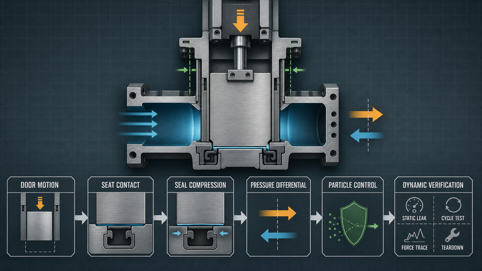
A vacuum gate valve or slit valve must preserve a vacuum boundary while repeatedly moving a door or gate plate into and away from a valve seat. Reliability is therefore a coupled problem involving door geometry, seat condition, seal compression, guide accuracy, actuator repeatability, pressure differential, temperature, motion and cleanliness.
A gate valve commonly isolates two vacuum regions or a vacuum region from atmosphere. A slit valve performs the same basic isolation function through a restricted transfer opening, where the door path and guide envelope are more constrained. In both cases, the door, valve seat, seal groove, seal element, housing, guide and actuator must be evaluated as one sealing system.
A door can reach the commanded closed position and still be locally misaligned, under-compressed, over-compressed or rubbing the seat. A static helium leak test can pass while cycling produces particles, dynamic leakage or rising actuation force. Static leakage, dynamic contact, particle release, outgassing and cycle life are separate evidence streams.
The correct reliability statement must distinguish design judgment, engineering estimate, laboratory observation, model inference and field data. No seal material, coating or valve architecture removes leakage and particle risk under every pressure, temperature, motion and maintenance condition.
Vacuum Gate and Slit Valve Architecture
The valve body and housing carry pressure loads and locate the sealing interface. The door or gate plate provides the moving boundary. The valve seat defines the mating contour and sealing line. A seal groove controls the position and deformation of an elastomeric or polymer element. A metal seal may be formed, captured or integrated into the door or seat. The actuator, drive shaft or linkage creates the motion; guides, stops and datums control parallelism and closed-position repeatability. Purge or vent interfaces may equalize trapped pressure or control contamination, but they do not replace the primary door-to-seat seal.
Door, Seat and Seal Contact Mechanism
A reliable closure requires a repeatable door position, controlled parallelism, suitable surface flatness and a continuous sealing line. Seal compression provides conformity and recovery. Under-compression can leave local gaps and reduce pressure reserve. Over-compression can increase closing force, rubbing, compression-set loss and seal damage. The acceptable compression range is specific to the actual seal, groove, surfaces, temperature and pressure envelope; it is not a universal value.
Door tilt, seat deformation, groove error, coating damage or a trapped particle can create a local high spot or local gap. Pressure differential may assist contact in one direction while increasing opening force, shear or guide reaction in another. The closure sequence must therefore be checked in both the final position and the path used to reach and release it.
Static seals isolate non-moving interfaces. Dynamic sealing contacts must tolerate relative motion, friction and position variation. Elastomer seals provide compliance but may show compression set, hardening, swelling, extrusion, outgassing or wear. Polymer seals may reduce friction in selected designs but can generate transfer film or debris. Metal seals can provide a low-permeation boundary in defined architectures, but scratches, dents, particles, misalignment and over-compression can create permanent defects.
Table I: Vacuum Gate and Slit Valve Failure Mechanisms
|
Failure mechanism |
Primary stressor |
Local physical effect |
Typical symptom |
Recommended validation |
| Door misalignment | Guide or linkage error | Uneven contact | Local leak or rubbing | Position map and contact inspection |
| Insufficient compression | Position error or seat set | Incomplete sealing line | Static or pressure-dependent leak | Compression and leak check |
| Excessive compression | Stack-up or stop error | High local stress | High force or seal damage | Force trace and contact map |
| Seat wear | Sliding contact or particles | Profile loss | Leakage trend and debris | Cycle test and teardown |
| Seat deformation | Pressure, heat or impact | Local gap or high spot | Position-dependent leak | Flatness and thermal check |
| Compression-set loss | Dwell, heat and cycling | Lower recovery force | Leak after dwell or restart | Recovery and leakage test |
| Seal hardening or swelling | Heat, chemistry or cleaning | Loss of conformity or size change | Leak, force rise or extrusion | Hardness, dimensions and compatibility |
| Seal extrusion | Pressure and clearance | Edge nibbling or displacement | Debris and leakage | Pressure-cycle test |
| Door rubbing | Tilt, preload or guide wear | Scratch and friction debris | Force spike and particles | Motion trace and microscopy |
| Guide wear | Side load or abrasion | Door play and tilt | Repeatability loss | Clearance and cycle test |
| Actuator position error | Backlash or sensor drift | Over- or under-travel | Intermittent leak | Door-side position check |
| Metal seal damage | Scratch, particle or overload | Permanent defect | Persistent leakage | Surface microscopy |
| Lubricant migration | Excess or wrong location | Vacuum-side residue | RGA change or particles | Lubricant audit and RGA |
| Coating damage | Contact, impact or chemistry | Exposed substrate and debris | Wear track or contamination | Coating inspection |
| Repeated-cycle leakage | Accumulated wear or drift | Reduced contact reserve | Leakage after cycling | Dynamic leak and cycle test |
| Installation contamination | Poor cleaning or handling | Particle at sealing line | Immediate leak or excursion | Cleanliness audit and recheck |
A leakage trend is a symptom, not a mechanism. Door position, pressure state, force trace, contact evidence and teardown morphology are needed to separate seat wear, seal damage, misalignment and foreign material.
Pressure, Temperature and Motion Effects
Pressure differential changes door load, seat reaction, seal shear and actuator release force. Direction, exposed area, ramp and dwell matter. Temperature changes door and seat dimensions, seal modulus, recovery and friction. Thermal cycling can shift alignment when materials expand differently. Bakeout may accelerate compression set, hardening, swelling, lubricant migration or coating degradation.
Motion adds acceleration, stop impact, frictional heat and guide reaction. High speed may increase wear and debris; low speed may expose stick-slip. Repeated opening and closing accumulates sliding distance, compression history and contamination opportunity. Cycle count alone is not transferable life data; the pressure, temperature, speed, dwell, alignment and failure criterion must also be recorded.
Table II: Pressure, Temperature and Motion Influence Matrix
|
Stress factor |
Primary effect |
Secondary effect |
Potential failure mode |
Required measurement |
Main modeling limitation |
| Pressure differential | Door load and seat reaction | Release force and seal shear | Internal leakage | Pressure, direction and area | Nominal pressure hides local load |
| Pressure ramp | Transient force | Guide and actuator response | Impact or seal shift | Ramp and position trace | Static pressure is insufficient |
| Temperature | Dimensions and modulus | Friction and recovery change | Set, hardening or leak | History and material state | Average temperature hides gradients |
| Bakeout | Material and lubricant aging | Coating and guide change | Outgassing or particles | Peak, dwell and cycles | Rating may not represent assembly |
| Thermal cycling | Differential expansion | Alignment movement | Seat deformation | Range, rate and dwell | Cycle count lacks amplitude |
| Door acceleration | Guide and stop reaction | Transient contact load | Rubbing or impact | Acceleration profile | Speed omits transients |
| Closing speed | Friction and impact | Seal deformation rate | Sliding wear | Speed, stroke and force | Average speed hides path |
| Door parallelism | Nonuniform contact | Local stress concentration | Local leak or wear | Angle, flatness and map | One datum may miss tilt |
| Guide clearance | Lateral movement | Seal side load | Misalignment | Play and repeatability | Nominal fit hides wear |
| Vibration | Interface micro-motion | Wear and debris | Dynamic leak | Frequency and amplitude | Field spectrum may vary |
| Foreign particle | Local gap and point load | Scratching and debris cascade | Leak and contamination | Location and composition | Sampling may miss events |
| Actuator repeatability | Closed-position variation | Compression variation | Repeated-cycle leak | Position, force and backlash | Drive data may miss door position |
Pressure changes contact load, temperature changes material and geometry, motion accumulates damage, and alignment decides where the load is concentrated.
Particle Generation and Contamination Control
Particles may originate from door-to-seat rubbing, seal sliding contact, seat wear, seal-edge damage, guide wear, drive wear, lubricant migration, coating loss, metal contact, cleaning residue, assembly handling or foreign material trapped at the sealing line.
A foreign particle can interrupt the seal and create a point load. Subsequent rubbing may damage the seal, seat or coating and release more debris. Excessive contact pressure increases friction and wear; unstable or insufficient contact can create micro-slip and repeated impact. The target is controlled contact, not maximum compression.
Lubricant location, quantity, volatility and compatibility must be controlled. Cleaning residue can change friction, soften a polymer, attack a coating or become a volatile source. Clean components can be contaminated during seal seating, guide installation or actuator integration. Low outgassing, low particles and long cycle life require separate verification.
Vacuum Integrity, Leakage and Cleanliness Verification
Static helium leak testing verifies a stationary boundary. Dynamic leak testing observes the seal while the door moves or pressure changes. Vacuum hold and pressure-rise tests may combine leakage, outgassing, permeation and virtual leaks. Door closed-position repeatability and seat-contact inspection check whether the physical interface matches the commanded position.
Particle monitoring should record sampling location, size range, background, motion profile and pressure state. Residual gas analysis addresses volatile contamination rather than mechanical leakage. Actuation-force monitoring can reveal rubbing, guide wear, swelling or misalignment but cannot identify the mechanism alone. Cycle-life testing should define leakage, force, particle, position and visible-damage failure criteria. Post-test teardown identifies wear tracks, impressions, scratches, debris and coating damage.
After replacing a door, seat, seal, guide, actuator or lubricant, repeat the checks that match the changed risk. A static leak check alone is insufficient when dynamic contact or cleanliness has changed.
Table III: Vacuum Valve Sealing and Particle Verification Guide
|
Test or inspection |
Test purpose |
Key variable |
Detectable failure |
Suitable stage |
Main limitation |
| Static helium leak | Verify stationary boundary | Leak, pressure, temperature | External or static internal leak | Assembly and baseline | No motion representation |
| Dynamic leak test | Observe moving seal | Position, speed, pressure | Motion-induced leak | Design and troubleshooting | Needs representative path |
| Vacuum hold or pressure rise | Assess chamber response | Time, volume and baseline | Leak, outgassing or permeation | System verification | Sources may be mixed |
| Closed-position repeatability | Verify door placement | Position, backlash and cycles | Misalignment or variable compression | Integration and maintenance | Drive position may differ |
| Seat contact inspection | Check sealing-line continuity | Impression, flatness and particles | Gap, high spot or trapped material | Assembly and teardown | Can be qualitative |
| Particle monitoring | Detect released debris | Location, size and cycle profile | Wear, coating loss or contamination | Cleanliness testing | Sampling may miss events |
| Residual gas analysis | Identify volatile sources | Spectrum, pressure and temperature | Lubricant or cleaning residue | Material and system test | Not a leak diagnosis alone |
| Force monitoring | Track friction and release | Force, torque and position | Rubbing, guide wear or swelling | Integration and life test | Pressure effects require separation |
| Cycle-life test | Evaluate repeated operation | Motion, pressure, temperature, cycles | Wear, force drift or repeated leak | Qualification | Configuration-specific |
| Thermal or bakeout test | Check temperature exposure | Range, dwell and gas load | Set, hardening, outgassing or particles | Qualification | One cycle proves little |
| Post-test teardown | Confirm physical mechanism | Tracks, cracks, debris and damage | Seat, seal, guide or coating failure | After test or failure | Destructive |
| Post-maintenance verification | Confirm restored state | Alignment, leak, force and particles | Installation-induced failure | Repair release | Scope must match change |
No single test proves complete valve reliability. The evidence must connect stationary leakage, moving contact, particles, force behavior, cycle history and physical inspection.
Data Interpretation and Maintenance Planning
Record valve type, door and seat materials, seal material and geometry, contact-surface condition, alignment, closed position, closing force, pressure differential, temperature, bakeout condition, speed, cycle count, actuation force, leakage trend, particle result, residual-gas result, cleaning history, maintenance history and teardown morphology.
A rising force with stable static leakage may indicate guide wear, rubbing or seal swelling. Particles without immediate leakage may indicate coating or guide damage. A pressure-rise change with a new gas signature may indicate outgassing or lubricant migration. Maintenance may be calendar-, cycle-, condition-, leakage-trend-, particle-trend- or risk-based. Laboratory cycles must not be converted directly into field years.
Replacing a seat or seal requires confirmation of orientation, groove seating, surface condition, alignment, actuator position, stops, lubrication and cleanliness. Requalification should include dynamic checks when the changed part participates in motion or contact.
FMEA Risk Analysis
The FMEA includes physical sealing, motion, contamination, installation and verification risks. The RPN values below are illustrative engineering risk rankings, not field statistics or experimental results.
Table IV: Vacuum Gate and Slit Valve Sealing FMEA and RPN Analysis
|
Failure mode |
Cause |
Local effect |
System effect |
Detection method |
RPN |
Corrective action |
| Door misalignment | Guide or datum error | Uneven contact | Internal leakage | Position and contact map | 190 | Restore alignment |
| Insufficient compression | Position error or seat set | Local gap | Pressure-dependent leak | Compression and leak test | 185 | Correct closure position |
| Excessive compression | Stack-up or stop error | High local stress | Force rise and wear | Force trace | 175 | Control stops and preload |
| Seal wear | Sliding or abrasive contact | Section loss and debris | Dynamic leak and particles | Cycle test and teardown | 180 | Control path and surface |
| Compression-set loss | Dwell, heat and cycling | Lower recovery | Leak after restart | Recovery test | 170 | Review material and dwell |
| Seal hardening | Thermal or chemical aging | Reduced conformity | Surface-sensitive leak | Hardness and recovery | 150 | Verify exposure boundary |
| Seal swelling | Incompatible medium or cleaner | Size and friction change | Force rise or extrusion | Dimensions and compatibility | 155 | Control chemistry |
| Seal extrusion | Pressure and clearance | Edge displacement | Debris and leakage | Pressure cycle and teardown | 180 | Improve support and clearance |
| Seat deformation | Pressure, heat or impact | Local gap or high spot | Position-dependent leak | Flatness and thermal check | 175 | Review seat support |
| Door rubbing | Tilt, preload or guide wear | Scratches and debris | Particle event and damage | Force and microscopy | 185 | Correct motion path |
| Guide wear | Side load or abrasion | Door play | Repeatability loss | Clearance and cycling | 165 | Improve guide control |
| Actuator position error | Backlash or sensor drift | Over- or under-travel | Intermittent leak | Door-side position check | 175 | Calibrate and verify |
| Metal seal damage | Scratch, particle or overload | Permanent defect | Persistent leakage | Microscopy | 190 | Protect and control installation |
| Lubricant contamination | Excess or migration | Vacuum-side residue | Outgassing or particles | RGA and audit | 160 | Define location and quantity |
| Particle generation | Wear, rubbing or coating loss | Debris release | Process contamination | Particle monitoring | 185 | Remove source and requalify |
| Coating damage | Contact, impact or chemistry | Exposed substrate | Particles and friction change | Surface inspection | 155 | Control counterface |
| Foreign particle at seal | Poor cleaning or handling | Point load and gap | Leakage and debris cascade | Particle and contact review | 180 | Improve clean assembly |
| Repeated-cycle leakage | Wear, fatigue or drift | Lost contact reserve | Vacuum isolation loss | Dynamic trend and cycling | 195 | Verify mechanism and life |
| Incorrect cleaning | Residue or wrong chemistry | Friction or volatile change | Particles or outgassing | Cleaning audit and RGA | 145 | Qualify cleaning process |
| Incorrect seal installation | Damage, orientation or seating error | Local compression error | Immediate or delayed leak | Assembly inspection | 185 | Controlled installation |
| Insufficient post-maintenance verification | Static check only | Hidden dynamic risk | Recurring leak or contamination | Requalification audit | 175 | Match checks to changed risk |
Corrective action should improve the physical mechanism, assembly control and verification rule. Reducing an RPN without improving evidence does not improve reliability.
Conclusion
Vacuum gate and slit valve sealing begins with the geometry and load path between the door and the valve seat. The door must reach a repeatable position with controlled parallelism and contact force. The seat and seal must provide a continuous line without excessive friction, extrusion, local overstress or permanent damage.
Compression and contact force must balance leakage margin against particle risk. Door alignment, guides, actuator repeatability, pressure differential, temperature, motion and cleanliness jointly determine life. Particle control cannot be separated from door motion and seat contact.
Static helium leak testing is necessary but cannot replace dynamic leakage, particle monitoring, force measurement, cycle testing and teardown. After maintenance, cleanliness, installation, alignment, door position and vacuum performance must be re-established within the actual tested envelope.
Engineering FAQ
Q:How does a vacuum gate valve create a reliable sealing boundary?
A:The door reaches a repeatable position, remains aligned with the seat and creates a continuous contact line under the specified pressure and temperature conditions. Body, seat, guides, actuator and seal must be evaluated together.
Q:What is the difference between door, seat and seal failure?
A:Door failure concerns position, flatness, parallelism or rubbing. Seat failure concerns profile loss or deformation. Seal failure concerns loss of recovery, hardening, swelling, extrusion, cracking or wear. Contact evidence, force, leakage and teardown separate the mechanisms.
Q:Why can a valve pass a static helium leak test but generate particles during cycling?
A:Static testing does not reproduce sliding, acceleration, guide reaction, release force or repeated compression. Cycling can produce rubbing, guide wear, coating loss, seal debris or damage from trapped particles.
Q:How does door alignment affect vacuum valve sealing?
A:Alignment determines whether the door loads the seat uniformly. Tilt or guide play can create over-compression on one side and under-compression on another, causing leakage, force variation and wear.
Q:Which tests are needed after replacing a valve seat or seal?
A:Verify installation, surface condition, cleanliness, closed-position repeatability and static leakage. If the part participates in motion, add force, dynamic leakage, representative cycling and particle checks.
Q:How can particle generation be distinguished from ordinary vacuum leakage?
A:Leakage is a gas-flow or pressure-response condition; particle generation is a contamination-release condition. Use dynamic leakage, particle monitoring, force traces, residual-gas analysis, contact inspection and teardown together.
Post time: Aug-28-2026