
Executive Summary
A vacuum motion feedthrough must transmit displacement, rotation or combined motion while preserving a vacuum boundary and controlling contamination. Unlike a static flange, it is exposed to motion-induced friction, bellows strain, shaft alignment error, pressure differential, guide reaction, thermal movement, outgassing and particle generation. A connection that passes a static leak check may still lose performance during stroke, rotation or stop-start operation.
Bellows and sliding-shaft architectures solve the boundary problem differently. A bellows can isolate motion without a sliding contact across the vacuum wall, but its convolution geometry, end constraints, lateral offset and cycle history govern fatigue and buckling risk. A sliding shaft can transmit compact linear or rotary motion, but requires controlled dynamic contact, surface condition, guide support and friction management. Vacuum integrity and motion transmission must therefore be evaluated as separate but coupled functions.
Low outgassing and low particle generation are also reliability requirements. Volatile residues, lubricant migration, permeation, seal wear and motion debris can contaminate the chamber even when the pressure rise is acceptable. The correct engineering sequence is to define the architecture, map pressure and motion loads, control alignment and materials, verify static and dynamic behavior, then use maintenance evidence to update the reliability boundary.
Vacuum Motion Feedthrough Architecture
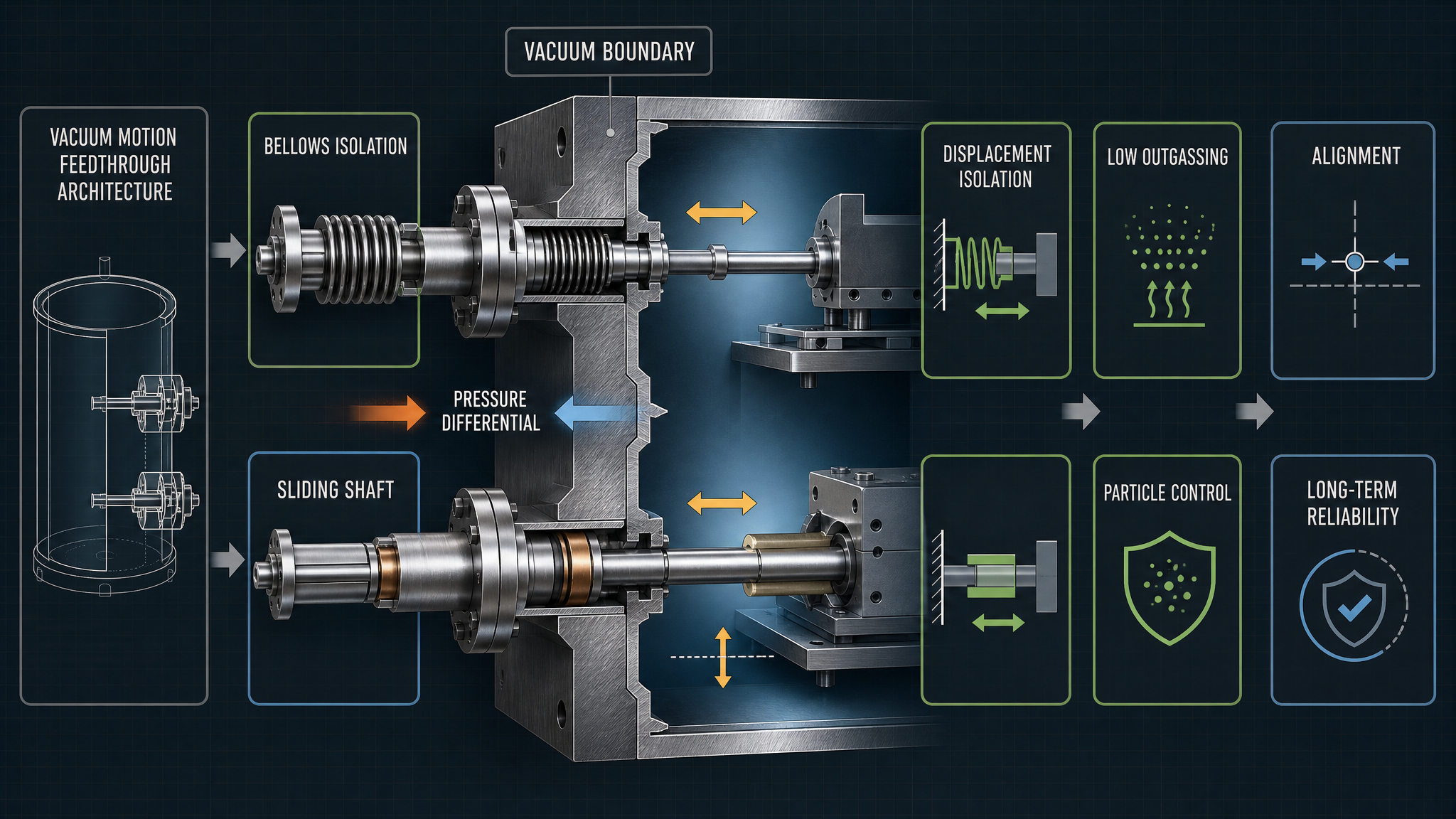
A motion feedthrough typically includes a vacuum chamber interface, static flange seal, bellows or sliding shaft, dynamic seal where required, guide bushing, bearing or support, retainer, atmospheric-side housing and a vacuum-side moving component. The interface must transmit the intended motion without allowing the pressure differential to create an uncontrolled load path or damaging contact condition.
Bellows-based designs provide displacement isolation through elastic deformation of the convolution set. The moving component can be connected to the bellows end without a shaft sliding through the vacuum boundary. Sliding-shaft designs instead use a controlled interface between the shaft and a seal or sleeve. They may be compact and compatible with linear, rotary or combined motion, but the dynamic contact must tolerate surface variation, guide reaction and pressure-driven force.
The architecture should distinguish static boundary sealing, motion transmission, guidance, load support and contamination control. A static flange seal may be reliable while a dynamic seal wears. A bellows may remain leak-tight while its end support receives excessive bending. A guide may preserve alignment but generate particles. These functions should not be collapsed into one generic “vacuum seal” rating.
Bellows Mechanics and Displacement Isolation
Bellows loading includes axial compression, axial extension, lateral offset, angular misalignment, bending, torsion and pressure-induced force. The allowable displacement depends on effective length, convolution geometry, material state, end constraints and the movement path. A bellows that tolerates a single static offset may experience a different stress history when the same offset is repeated at a defined stroke and frequency.
Lateral motion and angular error can transfer bending moment to the end connection. Excessive compression can promote contact between convolutions or local instability; extension can increase membrane and convolution stress; combined lateral and axial motion can concentrate strain at formed or welded regions. Pressure differential adds an axial force that may change guide reaction and actuator force. Dwell time, cycle frequency and stop positions influence recovery and fatigue history.
Static displacement capacity is not equivalent to stroke life. A defensible evaluation records the displacement components, pressure state, cycle definition, temperature, end constraint, acceleration and post-test morphology. Wall thickness, convolution count, rated stroke and cycle life must be taken from the actual design; they are not universal values.
Table I: Vacuum Motion Feedthrough Failure Mechanisms
|
Failure mechanism |
Primary stressor |
Local physical effect |
Typical symptom |
Recommended validation |
| Bellows fatigue crack | Repeated strain at convolution or end | Crack initiation and growth | Delayed vacuum leakage | Stroke-cycle test and teardown |
| Over-compression | Excessive axial travel or stop error | Convolution contact and local stress | Force rise or deformation | Displacement-limit test and inspection |
| Bellows buckling | Lateral load or poor support | Unstable convolution shape | Misalignment or rapid damage | Combined-load assessment |
| Excessive lateral displacement | Offset or angular error | End bending and uneven strain | Guide load or leak after cycling | Alignment and lateral-cycle test |
| Sliding-seal wear | Repeated contact and relative motion | Material removal and debris | Dynamic leakage trend | Dynamic leak test and teardown |
| Stick-slip | Low speed, high friction or poor lubrication | Irregular motion and force spikes | Force oscillation or position error | Low-speed actuation monitoring |
| Shaft surface damage | Roughness, burr or contamination | Leak path and abrasive contact | Leakage with wear track | Surface inspection and microscopy |
| Guide wear | Insufficient support or particle abrasion | Radial play and shaft tilt | Rising force or seal wear | Guide inspection and alignment check |
This table separates bellows deformation, dynamic contact, shaft condition and guide behavior. The symptom alone does not identify the mechanism; displacement history and post-test morphology are needed to distinguish fatigue, wear, instability and alignment-driven damage.
Sliding Shaft Sealing and Dynamic Contact
A sliding-shaft feedthrough must control shaft surface finish, hardness, straightness, concentricity, seal interference, contact pressure, speed, stroke, lubrication condition and guide support. The shaft may move axially, rotate or combine both motions. Each path changes the contact history and can alter frictional heat, wear debris and seal deformation.
A shaft surface defect can become a leakage channel or accelerate seal damage. Insufficient guide support allows the shaft to tilt and transfers side load into the dynamic seal. Low-speed motion can produce stick-slip when static friction is higher than running friction; higher speed can increase frictional heat, lubricant migration and particle generation. Seal extrusion or compression-set loss can reduce contact pressure, while excessive interference can increase actuation force and wear.
The vacuum side and atmospheric side may impose different pressure conditions on the contact. Differential pressure can change the net axial force, lip loading and friction reserve. Static vacuum hold results do not represent these changes during motion. Dynamic sealing evidence must include the actual stroke or rotation, speed, acceleration, dwell and guide condition.
Differential Pressure, Motion and Load Interaction
Vacuum-to-atmosphere pressure differential creates a force on any moving area exposed to the boundary. The force direction, shaft diameter, bellows effective area, guide friction and actuator path determine how much load reaches the seal or support. Motion acceleration can amplify guide reaction, while stop-and-start operation can create transient force and stick-slip.
Thermal expansion changes shaft clearance, housing position, seal modulus and bellows length. Structural resonance or vibration can add micro-motion even when the commanded stroke is unchanged. A single static leak value therefore cannot represent all motion states. The test envelope should combine pressure differential, temperature, motion profile, alignment, support and vibration where those factors coexist in service.
Table II: Pressure, Motion and Alignment Influence Matrix
|
Stress factor |
Primary effect |
Secondary effect |
Potential failure mode |
Required measurement |
Main modeling limitation |
| Pressure differential | Net force across moving boundary | Seal and guide load change | Dynamic leakage or force rise | Vacuum level and exposed area | Static pressure hides motion load |
| Axial stroke | Bellows strain or sliding distance | Wear and fatigue accumulation | Crack or seal wear | Stroke, speed and cycles | Cycle count lacks amplitude |
| Lateral offset | Bending and guide reaction | Seal edge loading | Misalignment leakage | Offset, angle and force | Fixture may be idealized |
| Rotation | Circumferential contact motion | Heat and debris generation | Wear or stick-slip | Speed, torque and cycles | Rotary path differs from stroke |
| Acceleration | Transient guide and seal load | Impact at stops | Extrusion or damage | Acceleration and stop profile | Nominal speed is insufficient |
| Temperature | Modulus and clearance change | Lubrication and outgassing change | Seal loss or bellows stress | Temperature history and dwell | Material response may change |
| Vibration | Micro-motion and resonance | Particle and wear increase | Motion-induced leakage | Frequency, amplitude and spectrum | Field spectrum may be uncertain |
| Guide friction | Lateral restraint and force | Load transfers to seal | Excessive actuation force | Force or torque trace | Friction is path-dependent |
The matrix defines interacting loads rather than a single static boundary value. Modeling limits must be stated because the same nominal vacuum and stroke can produce different results when alignment, acceleration, temperature or guide friction changes.
Low-Outgassing and Cleanliness Control
Low outgassing is a system property affected by material formulation, cleaning, surface condition, temperature, vacuum level and motion. Volatile additives, residual cleaning agents, lubricant migration and permeation can raise chamber background or contaminate sensitive surfaces. Dynamic friction adds another source: wear debris and seal fragments can be generated even when the material has low vapor release in a static condition.
A material name is not a complete outgassing qualification. The relevant evidence depends on the vacuum environment, temperature exposure, bakeout, preconditioning, motion profile and acceptance indicator. Residual gas analysis can identify volatile species or trends, while particle inspection and teardown address a different risk. Low outgassing, low particles and long stroke life should be verified separately and then assessed together.
Lubricants and coatings require particular control. Migration can contaminate the vacuum side, while insufficient lubrication can increase friction, stick-slip and debris. Cleaning residue can behave as a volatile source or alter contact. No material should be described as producing zero outgassing under every vacuum level and motion condition.
Seal Materials and Interface Protection
Material and interface selection depends on architecture. Metal bellows can provide a deformation-based boundary without a sliding seal, but they still require fatigue, end-joint, cleanliness and displacement verification. Elastomeric dynamic seals may provide compliant contact but can show permeation, compression-set loss, outgassing, swelling or particle generation. PTFE-based and filled polymer elements can reduce friction in some designs, but filler, surface and counterface compatibility must be evaluated.
Metal static seals, coated shafts, hard-coated guide surfaces, ceramic guides, non-metallic guide elements and low-outgassing lubricants each address different functions. The comparison should include vacuum and temperature boundary, pressure differential, speed, stroke, friction, wear, outgassing, particles, chemical compatibility, installation and maintenance. A material that performs well in a static coupon test may not retain that behavior during combined motion and vacuum exposure.
Interface protection includes controlled surface finish, clean assembly, protected counterfaces, guide support, contamination barriers and defined limits on lubricant use. The protection strategy should identify which component is intended to carry motion, which component carries pressure load and which surface is allowed to wear.
Inspection, Testing and Maintenance
Static helium leak testing establishes a baseline for the stationary vacuum boundary. Dynamic leak testing observes leakage during stroke or rotation. Vacuum hold and pressure-rise tests show system response, while residual gas analysis can identify volatile contamination that is not equivalent to a leak. Particle inspection addresses cleanliness and wear debris. Stroke-cycle or rotary-cycle testing evaluates fatigue, wear, force change and motion-induced leakage.
Alignment inspection should record shaft position, concentricity, guide condition, bellows end constraint and surface condition. Friction or actuation-force monitoring can reveal stick-slip, guide wear or increased seal contact. Bellows visual inspection and fatigue evaluation should be followed by teardown when the test objective includes crack initiation or convolution damage. Surface roughness inspection and contamination analysis help connect a leak or particle result to a physical mechanism.
After maintenance, clean the interface using a controlled process, inspect the bellows or shaft, verify guide and seal installation, restore the defined lubricant condition and repeat the applicable vacuum and motion checks. A static leak test after replacement is necessary but may not be sufficient if the maintenance changed alignment, stroke, surface condition or contamination exposure.
Table III: Vacuum Motion Feedthrough Test and Verification Guide
|
Test or inspection |
Test purpose |
Key variable |
Detectable failure |
Suitable stage |
Main limitation |
| Static helium leak test | Verify stationary boundary | Leak signal and vacuum state | External static leakage | Assembly and baseline | Does not represent motion |
| Dynamic leak test | Observe leakage during movement | Stroke, speed and pressure | Motion-induced leakage | Qualification and service | Requires representative motion |
| Pressure-rise test | Assess chamber response | Time, volume and initial state | Leak, outgassing or permeation trend | System verification | Sources may be mixed |
| Residual gas analysis | Identify volatile species | Spectrum, temperature and time | Outgassing or lubricant migration | Material and system test | Needs interpretation and baseline |
| Particle inspection | Assess contamination | Size, count and location | Wear debris or seal fragments | Cleanliness and teardown | Sampling may miss transient particles |
| Stroke or rotary cycle | Assess motion life | Amplitude, speed and cycles | Fatigue, wear and force drift | Design validation | Life is configuration-specific |
| Force or torque monitoring | Detect friction change | Actuation force and waveform | Stick-slip, guide wear or extrusion | Integration and life test | Fixture friction can interfere |
| Alignment inspection | Control guide and shaft load | Offset, angle and surface | Misalignment and edge loading | Assembly and maintenance | Requires defined datum |
| Post-test teardown | Confirm morphology | Cracks, tracks, debris and deformation | Mechanism classification | After qualification or failure | Destructive and sample-based |
The verification guide keeps vacuum integrity, volatile contamination, particles, motion life and alignment as separate evidence streams. The complete conclusion should be based on their relationship, not on one favorable test result.
Data Interpretation and Maintenance Planning
Record bellows material and geometry, shaft material and diameter, surface condition, seal material, guide structure, vacuum level, pressure differential, temperature, stroke or rotation, speed, acceleration, cycle count, dwell, leakage trend, actuation force, outgassing result, particle result, alignment, teardown morphology and cleaning or assembly history. These records define the tested envelope and allow a failure to be classified as bellows fatigue, dynamic wear, guide error, contamination or installation damage.
Maintenance may be calendar-based, cycle-based, condition-based, vacuum-performance-based or risk-based. A rising actuation force, changing pressure-rise trend, new residual-gas signature, particle increase or alignment shift can trigger inspection before complete functional loss. Laboratory cycle count is evidence for the tested configuration; it is not a direct conversion to field service years.
Post-maintenance requalification should match the changed risk. A bellows replacement may require static and dynamic leak checks; a shaft or guide replacement may require alignment, surface and force checks; a seal or lubricant change may require outgassing and particle verification. Document the changed parts, cleaning history, motion envelope and acceptance basis.
FMEA Risk Analysis
The RPN values below are illustrative engineering risk rankings, not field statistics or experimental results. They prioritize investigation across vacuum boundary integrity, motion function, cleanliness and maintenance control. Actual severity, occurrence and detection values must be assigned from the specific feedthrough design and service history.
Table IV: Vacuum Motion Feedthrough Sealing FMEA and Illustrative RPN Analysis
|
Failure mode |
Cause |
Local effect |
System effect |
Detection method |
RPN |
Corrective action |
| Bellows fatigue crack | Repeated strain or end constraint | Crack growth | Vacuum loss and downtime | Cycle test and teardown | High | Review strain path and limits |
| Bellows over-compression | Stop error or excess stroke | Convolution contact | Force rise or damage | Displacement inspection | High | Set travel stops and verify |
| Bellows buckling | Lateral load or poor support | Unstable shape | Misalignment and leak risk | Combined-load test | High | Improve support and alignment |
| Shaft misalignment | Guide or assembly error | Edge loading at seal | Dynamic leakage | Alignment and force check | High | Control datums and guide fit |
| Damaged shaft surface | Burr, roughness or contamination | Leak path and wear | Particle and vacuum risk | Surface inspection | High | Protect and finish counterface |
| Dynamic seal wear | Stroke, speed or poor lubrication | Contact loss and debris | Leakage and contamination | Dynamic test and teardown | High | Control wear envelope |
| Stick-slip | Static friction or low-speed motion | Force oscillation | Position error and seal damage | Force waveform | Medium | Review material, load and speed |
| Seal compression-set loss | Temperature, dwell or material change | Contact force decay | Leak during motion | Compression and leak check | Medium | Validate material and compression |
| Outgassing | Volatile residue or additive | Gas load at vacuum side | Pressure-rise and contamination | RGA and pressure-rise | High | Clean, precondition and qualify |
| Permeation | Material transport through seal | Slow gas or vapor flow | Background pressure drift | Pressure-rise and material study | Medium | Assess barrier and material boundary |
| Particle generation | Wear, cracking or poor cleaning | Debris at interface | Contamination and guide wear | Particle inspection | High | Control surfaces and cleaning |
| Lubricant migration | Excess or incompatible lubricant | Vacuum-side film | Contamination and RGA signal | RGA and surface inspection | High | Define lubricant quantity and location |
| Guide wear | Load, abrasion or particles | Radial play | Misalignment and seal wear | Guide inspection | Medium | Improve guide support and cleanliness |
| Incorrect installation | Wrong seal, retainer or orientation | Local boundary weakness | Leak or motion failure | Assembly audit and leak test | High | Use controlled assembly sequence |
| Inadequate cleaning | Residue or particles remain | Volatile or abrasive source | Vacuum contamination | Cleanliness and RGA checks | Medium | Qualify cleaning and handling |
| Motion-induced vacuum leakage | Combined load exceeds margin | Dynamic contact opens | Process interruption | Dynamic leak and force trend | High | Requalify combined envelope |
The FMEA separates bellows fatigue, dynamic sealing, guide behavior, contamination and installation causes. Corrective action should improve the physical boundary, motion path, cleanliness control or verification rule rather than simply replacing a seal.
Conclusion
Vacuum motion feedthrough sealing begins with architecture. Bellows provide a deformation-based displacement isolation path without requiring a sliding contact across the vacuum boundary, but fatigue, buckling, lateral offset, end constraint and pressure-induced load must be controlled. Sliding-shaft designs provide compact motion transfer, but require coordinated control of shaft surface, guide support, dynamic contact, friction and contamination.
Pressure differential, motion trajectory, temperature, acceleration, alignment and material state jointly determine seal load and vacuum integrity. Low outgassing and low particle requirements must be verified separately from motion life, then interpreted together with residual gas, particle, force, leakage and teardown evidence. Static leak testing is necessary but cannot replace dynamic leakage and cycle verification.
Reliable maintenance restores more than a physical part. It must restore alignment, surface condition, cleanliness, lubricant control, motion limits and vacuum verification. A defensible feedthrough qualification therefore distinguishes design judgment, engineering estimate, laboratory observation and field evidence, and updates the reliability boundary as operating history accumulates.
Engineering FAQ
Q:How does a bellows isolate motion while maintaining a vacuum boundary?
A:A bellows uses controlled elastic deformation of its convolutions to accommodate the specified motion while remaining a continuous pressure boundary. Its reliability depends on geometry, end constraints, pressure load, alignment and cycle history.
Q:Why can a sliding-shaft feedthrough leak only during motion?
A:Motion can change contact pressure, shaft alignment, friction, surface interaction and seal deformation. A static condition may not reproduce the dynamic gap or wear path that opens during stroke or rotation.
Q:What causes bellows fatigue in a vacuum motion feedthrough?
A:Repeated strain, excessive stroke, lateral offset, angular error, torsion, pressure-induced load and restrictive end constraints can concentrate stress. The actual cause requires displacement history and post-test morphology.
Q:How do low-outgassing materials affect dynamic seal selection?
A:They reduce one contamination source, but dynamic selection must also address friction, wear, particles, permeation, temperature, pressure differential, motion profile and cleaning. Low outgassing alone does not establish motion life.
Q:Can a static helium leak test prove dynamic sealing reliability?
A:No. It verifies the stationary boundary under the test condition. Dynamic leakage, stroke or rotary cycling, force monitoring and teardown are needed when motion changes the contact state.
Q:Which parameters should be recorded during a motion feedthrough life test?
A:Record vacuum level, pressure differential, temperature, stroke or rotation, speed, acceleration, dwell, cycle count, alignment, force or torque, leakage trend, gas signal, particles and teardown findings.
Post time: Aug-27-2026