
Executive Summary
Liquid-cooling control valves are reliability components in CDU and server loops. Internal, external or body leakage, loss of actuation or pressure-boundary failure can disturb flow, create thermal deviation or force a cooling-zone outage.
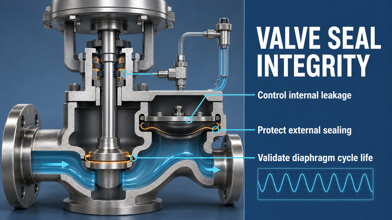
The seat, moving stem boundary and diaphragm face different loads. Seat reliability depends on contact stress, shut-off force, pressure differential, surface condition and particles. Stem reliability depends on motion, friction, alignment, finish and compression. Diaphragm reliability depends on flexing strain, pressure and temperature cycling, clamping and chemistry.
Reliability depends on valve type, motion, coolant, temperature, pressure, actuation frequency, surface condition, assembly and verification—not on material name alone.
Valve Seat Sealing and Internal Leakage
A valve seat is the contact interface intended to stop flow when the valve is closed. Internal leakage occurs when fluid passes through that closed interface. The closing force must create sufficient local contact stress to overcome the pressure-driven opening force and surface imperfections. If the pressure differential rises, the required shut-off force and local loading also change.
A closed valve can leak when the seat deforms, wears, erodes or contains a trapped particle. Throttling adds sliding, impact and local flushing; roughness or waviness can leave a leakage path, while high differential pressure can overload an unsupported soft seat.
Seat-leakage acceptance must follow the applicable valve specification, project requirement and defined test method. Leakage class or allowable leakage must not be inferred from this general guide alone; the valve type, size, pressure direction, test medium, temperature and measurement method must be stated.
Soft seats can provide low leakage when temperature, particles, pressure and deformation are controlled. Hard seats tolerate higher duty but require controlled geometry and finish. Composite seats balance compliance and strength within a defined envelope. Internal, external, body and diaphragm failures require different tests.
Table I: Valve Sealing Structure and Function Comparison
| Structure | Sealing location | Motion type | Main sealing function | Main failure mode | Suitable application | Main limitation |
| Soft-seat valve | Seat interface | Closing or throttling | Low internal leakage | Seat deformation or wear | Clean-fluid isolation and control | Sensitive to temperature, particles and pressure |
| Hard-seat valve | Seat interface | Closing or throttling | Durable shut-off interface | Wear, impact or surface damage | Higher mechanical or thermal duty | Requires tighter surface control |
| O-ring stem seal | Stem boundary | Reciprocating or rotary | External sealing | Wear, compression set or extrusion | Moderate stem motion | Friction and material limits |
| PTFE packing | Stem boundary | Reciprocating or rotary | External sealing with low friction potential | Packing wear or adjustment loss | Serviceable stem assemblies | Installation and compression control |
| Bellows-sealed stem | Stem boundary | Limited guided motion | External leakage isolation | Bellows fatigue or rupture | High external-leakage consequence | Stroke, fatigue and cost constraints |
| Diaphragm valve | Diaphragm boundary | Flexing stroke | Isolation and cavity separation | Fatigue, rupture or clamp damage | Clean or contamination-sensitive loops | Stroke and fatigue limits |
The comparison is application-dependent. Selection must include valve motion, pressure, temperature, coolant condition, leakage consequence and maintenance practice; no single structure is a universal solution for every liquid-cooling loop.
Valve Stem Sealing and External Leakage
The valve stem creates a dynamic pressure boundary. Reciprocating and rotary motion create different friction, wear and compression patterns. External leakage can begin with stem damage, compression loss, misalignment or actuator side load.
O-ring stem seals are compact but can experience wear, compression set or extrusion. PTFE packing can provide low-friction sealing when gland compression and surface finish are controlled, but adjustment and installation quality matter. Elastomer lip seals depend on orientation, interference and surface condition. Bellows-sealed stems remove a conventional sliding stem seal from the external boundary, but the bellows becomes a fatigue-sensitive pressure component. Double stem seals may provide additional protection, but the space between seals and the monitoring method must be defined.
Stem friction is both a sealing and control variable. Excessive friction can prevent full stroke or cause stick-slip motion. Check alignment, guides, eccentricity, finish and assembly torque before blaming seal material.
External-leakage inspection should identify the measured boundary: stem-to-gland interface, bonnet or body joint, bellows boundary, diaphragm clamp boundary or another defined pressure boundary. Different paths require different corrective actions.
Diaphragm Structure and Fatigue Reliability
A diaphragm valve uses a flexible diaphragm as a pressure boundary and actuation element. The diaphragm repeatedly flexes through its stroke, so its reliability depends on strain range, pressure cycling, temperature cycling, clamping geometry, material behavior and chemical exposure. Excessive stroke, sharp transitions at the clamping area, pressure pulses or uneven support can accelerate fatigue.
A diaphragm valve can reduce cavity retention and separate the actuator from coolant, but it retains fatigue limits. PTFE, EPDM, FKM, FFKM and composite diaphragms have different chemical, temperature, fatigue and manufacturing boundaries; selection must follow the actual coolant and duty cycle.
Diaphragm verification should combine actuation-cycle testing, pressure-hold testing, thermal cycling and post-test teardown. Inspection should look for cracks, thinning, permanent deformation, clamp damage, abrasion and changes in stroke force. Any cycle-life value must identify the valve, coolant, pressure, temperature, stroke and test method.
Post-test analysis should distinguish crack initiation, crack propagation, pinhole leakage, full rupture, permanent deformation and clamp-edge damage. These failure modes may require different changes to stroke, support, material, clamping or maintenance practice.
Material and Structural Selection
Valve selection should begin with the function and operating envelope. A soft-seat valve may be appropriate when low shut-off leakage is required and temperature, particles and pressure are controlled. A hard-seat valve may be preferred for higher mechanical or thermal duty. A bellows-sealed stem may be justified when external leakage consequence is high, while a diaphragm valve may be preferred when cavity separation or low fluid retention is important.
The decision must include coolant chemistry, temperature, pressure, differential pressure, actuation frequency, required shut-off performance, particle sensitivity, cleanliness requirements and maintenance access. Chemical compatibility is only one screening step. Mechanical wear, compression set, extrusion, fatigue, friction, surface damage and assembly repeatability can dominate the service life.
Testing and Maintenance
A valve seal qualification plan should separate internal leakage, external leakage, pressure integrity, actuation behavior and physical damage. Seat leakage tests should state pressure direction, temperature, coolant and closed position. External leakage tests should examine the stem, body, gland, bellows or diaphragm boundary separately. Pressure-hold tests should define pressure, duration and measurement resolution.
Actuation-cycle tests should record stroke, frequency, cycle count, friction, position response and leakage trend. Thermal-cycle and differential-pressure tests should expose the valve to defined combinations rather than isolated variables. Diaphragm fatigue testing should be followed by teardown analysis. Maintenance records should identify valve type, seal material, coolant, temperature, pressure, differential pressure, actuation frequency, cycle count, leakage result and test duration.
Table II: Valve Seal Failure Factors
| Failure factor | Local mechanism | Likely effect | Detection method | Recommended control |
| Pressure differential | Uneven load or extrusion force | Seat leakage or high actuation force | Differential-pressure test and friction trend | Define pressure direction and limits |
| Temperature | Expansion, softening or embrittlement | Compression loss or fatigue acceleration | Thermal-cycle and material review | Use validated temperature envelope |
| Actuation frequency | Repeated wear or fatigue exposure | Seat, stem or diaphragm life reduction | Cycle counter and leakage trend | Set duty-cycle limits and inspection |
| Coolant chemistry | Swelling, extraction or property change | Seal deformation or embrittlement | Fluid-property and post-test inspection | Validate material in actual coolant |
| Particle contamination | Particle trapped on seat | Internal leakage or surface damage | Inspection and leakage test | Control cleanliness and filtration |
| Stem alignment | Side loading and uneven compression | Stem friction or external leakage | Alignment and friction measurement | Guide stem and control assembly |
| Surface finish | Leak path or abrasive wear | Stem or seat leakage | Surface inspection and metrology | Specify finish and protect surfaces |
| Seal compression | Under-compression or extrusion | Leakage or high friction | Assembly inspection and teardown | Control gland and clamp process |
The same seal can behave differently when pressure, temperature, motion, coolant chemistry or assembly condition changes. Each control method should therefore be tied to a measurable parameter rather than to a material name alone.
Table III: Valve Seal Testing and Maintenance Matrix
| Test | Test objective | Key parameter | Failure signal | Verification output | Suitable maintenance stage |
| Seat leakage test | Verify closed-valve integrity | Pressure, direction and temperature | Measured internal leakage | Leakage record and acceptance decision | Design qualification and service release |
| External leakage test | Verify stem/body boundary | Stem position and pressure | Visible or measured external leak | Inspection and measurement record | Assembly and maintenance |
| Pressure-hold test | Verify pressure boundary | Pressure and duration | Pressure decay or wetting | Hold-test record | Post-repair verification |
| Actuation-cycle test | Assess dynamic wear | Stroke, frequency and cycle count | Friction rise or leakage change | Cycle and condition trend | Design validation |
| Thermal-cycle test | Assess expansion and fatigue effects | Temperature range and dwell | Leakage or stroke change | Thermal-cycle report | Qualification and material review |
| Diaphragm fatigue test | Assess repeated flexing | Stroke, pressure and cycles | Crack, rupture or leakage | Teardown and life record | Diaphragm qualification |
| Post-test teardown | Identify physical mechanism | Wear, damage and deposits | Seat, stem or diaphragm damage | Failure analysis record | Root-cause review |
No single test is sufficient: seat leakage, external leakage, pressure integrity, actuation behavior and teardown answer different reliability questions.
Any leakage, cycle-life or friction result must identify the coolant formulation, temperature, pressure, differential pressure, actuation frequency, valve size and test method. A result from one valve and fluid condition must not be treated as a lifetime guarantee for another system.
FMEA Risk Analysis
A valve-seal FMEA organizes failures causing internal or external leakage, control loss or recurrence after maintenance. It should cover seat wear/deformation, stem wear/misalignment, extrusion, diaphragm fatigue/rupture, particles, stroke error, excess pressure, thermal degradation and installation error.
The analysis should separate local effect from system effect. A small seat leak may become uncontrolled flow, thermal deviation, contamination or a maintenance outage depending on the valve function and isolation boundary. RPN is a prioritization aid, not a universal safety limit. The rankings below are illustrative engineering assessments, not certification results or field-failure statistics. Project values require documented Severity, Occurrence and Detection scales and the required Action Priority method where applicable.
Table IV: Valve Seal FMEA and RPN Analysis
| Failure mode | Cause | Local effect | System effect | Detection method | Illustrative RPN | Corrective action |
| Valve seat wear | Repeated throttling or particles | Increasing internal leakage | Flow-control or shut-off loss | Seat leakage trend and inspection | 165 | Control duty cycle and surface condition |
| Stem seal leakage | Wear, compression set or finish damage | External coolant leakage | Maintenance or safety exposure | External leakage and friction test | 170 | Validate seal, finish and alignment |
| Diaphragm fatigue | Excessive stroke or pressure cycling | Loss of pressure boundary | Loop outage or contamination | Cycle test and teardown | 180 | Limit stroke and validate fatigue |
| Seal extrusion | High differential pressure or poor support | Local seal damage | Leakage and actuation error | Pressure and teardown inspection | 155 | Improve support and pressure limit |
| Particle contamination | Particle trapped on sealing surface | Leak path or wear | Recurring leakage or control drift | Cleanliness and leakage inspection | 175 | Control openings and filtration |
| Excessive differential pressure | Wrong operating condition | High contact or actuator load | Stroke failure or leakage | Operating data and pressure test | 160 | Define pressure envelope |
| Actuator stroke error | Calibration, friction or misalignment | Incomplete closure or over-travel | Uncontrolled flow or seat damage | Position feedback and stroke test | 150 | Calibrate and verify stroke |
| Incorrect maintenance installation | Wrong part, orientation or compression | Immediate local seal issue | Repeat failure or outage | Part and post-maintenance test | 190 | Controlled installation and release gate |
All RPN values in this table are illustrative engineering assessments. They are not universal safety limits, certification results or field-failure statistics. High-priority actions should become design requirements, test controls and maintenance release criteria.
Conclusion
Valve-seal reliability combines seat contact stress, stem motion, diaphragm fatigue, coolant condition, pressure differential, temperature cycling, surface finish, alignment, actuator control and maintenance quality.
A reliable control-valve solution should provide stable shut-off, low internal leakage, low external leakage, controlled actuation force, adequate cycle life, low particle generation and a verifiable maintenance condition. These requirements must be demonstrated with defined leakage, pressure, cycle, thermal and post-test inspections under the actual valve type and coolant envelope.
Engineering FAQ
Q:What is the difference between valve seat leakage and stem leakage?
A:Seat leakage is flow passing through a valve that is intended to be closed. Stem leakage is coolant escaping along the moving stem boundary to the outside of the pressure boundary. They require different tests and corrective actions.
Q:How does differential pressure affect valve sealing reliability?
A:Differential pressure changes seat load, contact stress, actuator force and extrusion risk. Pressure direction and magnitude must be defined for closure, throttling, leakage testing and maintenance.
Q:When is a diaphragm valve preferable to an O-ring stem-sealed valve?
A:A diaphragm valve may be preferable when cavity separation, low retention or external stem-leakage control is important. It still requires validation of stroke, pressure cycling, chemical exposure, clamping and fatigue life.
Q:How can valve seal wear be detected before visible leakage occurs?
A:Use leakage trending, stem-friction measurement, position-versus-flow comparison, actuation-cycle records, pressure-hold checks and inspection of particles or wear debris. No single indicator is sufficient for every valve type.
Q:Which tests are necessary to validate long-term valve seal reliability?
A:Use seat and external leakage tests, pressure-hold tests, actuation-cycle tests, thermal-cycle tests, differential-pressure tests and post-test teardown. The test matrix must state valve type, coolant, temperature, pressure, frequency and cycle count.
Q:How do particles and coolant chemistry affect valve seat performance?
A:Particles can remain on the seat or abrade sealing surfaces, while coolant chemistry can change seal swelling, extraction, softening or embrittlement. Both must be evaluated with cleanliness control and material testing in the intended coolant.
Post time: Aug-19-2026