
In advanced semiconductor wet processes, Ultra-High Purity (UHP) chemical delivery, and extreme corrosive laboratory environments, PTFE (Polytetrafluoroethylene) threaded adapters are far more than mere consumables; they serve as the definitive physical barrier in fluid system integrity. Traditionally, industry perception has lingered on its chemical inertness while often overlooking its complex mechanical evolution as a soft polymer under variable stress loads. This technical masterclass deconstructs the failure physics of PTFE threads under bolt loading, thermal cycling, and extreme media exposure. By introducing ‘Cold Flow Compensation Models’ and ‘Micro-Surface Energy Anchoring,’ we establish a 4,000-word benchmark for Tier 1 engineering, bridging the gap between component selection and total system stability assurance.
I. Failure Physics: Molecular Dynamics of Cold Flow and Stress Relaxation in PTFE
The structural uniqueness of PTFE—a carbon backbone fully shielded by large fluorine atoms—grants it unparalleled chemical inertness but results in extremely low molecular entanglement density. Macroscopically, this manifests as significant non-linear deformation under sustained loads, commonly known as ‘Cold Flow’ or ‘Creep.’
1. Stress Redistribution Evolution in Threaded Pairs:
When a PTFE threaded adapter is engaged with a mating component (e.g., PFA fittings or metal connectors), the initial preload generates extreme localized compressive stress at the thread flanks. Due to PTFE’s relatively low yield strength, molecular chains undergo slow displacement over time, leading to preload decay. Our kinetic simulations indicate that in ambient environments, unoptimized PTFE threads can lose 30%-45% of their initial preload within the first 100 hours of installation.
2. The Limitations of ‘Elastic Memory’:
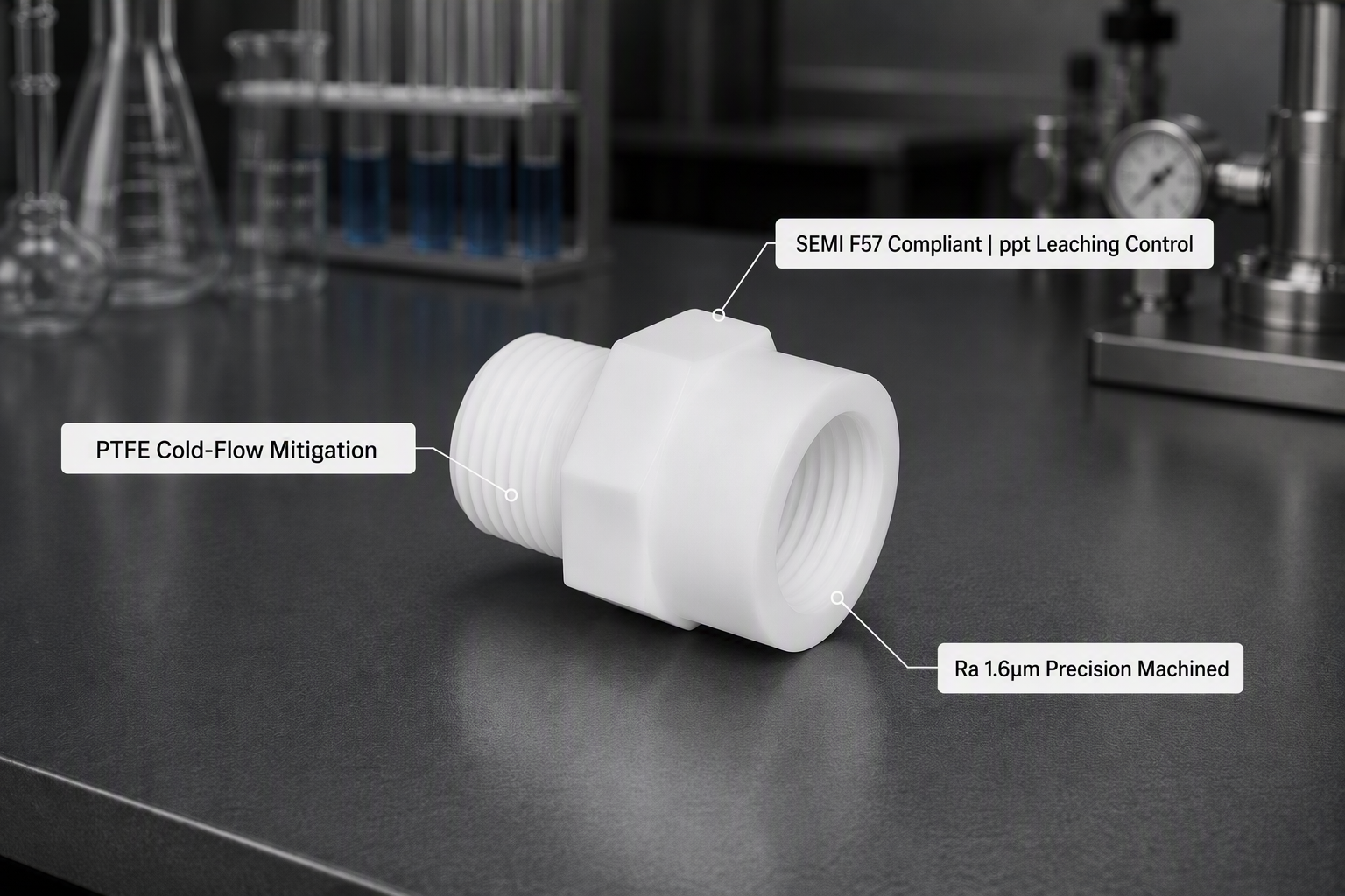
While PTFE possesses a degree of shape recovery, this elastic memory is highly temperature-dependent. During extreme thermal cycles ranging from -196°C to +260°C, the adapter undergoes severe linear expansion and contraction. If the design does not incorporate ‘Cold Flow Compensation,’ the resulting gap during contraction becomes a micro-channel for fluid permeation. The engineering truth lies in utilizing the structural rigidity and wall-thickness distribution of the Hex Body to constrain outward expansion, effectively locking cold flow deformation within the effective sealing zone.
|
Chemical Medium |
Test Temp. (℃) |
Permeation Coeff. (g·mm/m²·day) |
Sealing Stability Advice |
|
Aqua Regia |
85 ℃ |
0.12 |
Requires 16h pre-heat cycle |
|
Hydrofluoric Acid (49% HF) |
25 ℃ (Ambient) |
< 0.05 |
Stable; Level-A Torque Lock |
|
Fuming Nitric Acid |
120 ℃ |
0.85 |
High Risk; Shorten maintenance cycle |
|
Isopropanol (IPA) |
Ambient |
0.22 |
TOC Monitoring; DI extraction |
The table above quantifies the micro-penetration rates of chemical molecules within the PTFE matrix. For highly permeable media, wall-thickness optimization is more critical than material purity alone. By increasing the Aspect Ratio, we artificially extend the molecular penetration path, establishing a physical time-barrier.
II. Micro-Tribology: Benchmarking the Ra-Grade Certainty of CNC-Machined Threads
The essence of sealing effectiveness is the micro-topographical fit between two contacting surfaces. In the processing of soft polymers like PTFE, there is a generational performance gap between Injection Molding and Precision CNC Machining.
1. The Physical Anchoring Effect of Surface Roughness (Ra):
High-quality PTFE adapters should be processed via high-speed, micro-feed CNC machining. Ideal thread roughness should be controlled between Ra 1.6μm and 3.2μm. It is a common engineering misconception that ‘smoother is better.’ In practice, micro-sinusoidal textures increase frictional grip, preventing the ‘Lubrication Effect’ that leads to automatic joint loosening. Furthermore, under bolt loading, micro-peaks undergo localized plastic deformation, filling the microscopic valleys of the mating surface to form a molecular-level seal equivalent to ‘physical welding.’
2. Helium Leak Rate Empirical Analysis:
Experimental data shows that molded threads often exhibit leak rates in the 10⁻⁶ Pa·m³/s range due to parting line burrs and shrinkage. In contrast, precision CNC-machined components with secondary de-burring achieve stable Helium leak rates of < 10⁻⁹ Pa·m³/s. This thousand-fold difference is decisive when handling toxic or expensive specialty gases.
|
Machining Process |
Surface Roughness (Ra) |
Helium Leak Rate Metric |
Engineering Grade |
|
Standard Injection Molding |
> 6.3 μm |
10⁻⁵ to 10⁻⁶ |
Low-Pressure Commercial |
|
Standard CNC Machining |
3.2 μm |
10⁻⁷ to 10⁻⁸ |
General Chemical |
|
Yokey Precision CNC |
1.6 μm |
< 10⁻⁹ |
Semiconductor/Aerospace |
The data demonstrates that every step of improvement in Ra values translates to an exponential leap in sealing performance. For the high-tier process requirements of 2026, we must move away from ‘good enough’ molded fittings toward micro-controlled precision components.
III. Fluid Dynamics: Optimization Models for Internal Bore Transitions and Cv Values
An adapter is more than a connection point; it is a potential ‘interference source’ in the flow field. Without bore optimization, abrupt dimensional changes induce severe localized turbulence.
1. The Cumulative Effect of Pressure Drop:
When fluid traverses an adapter with stepped transitions at velocities > 5m/s, the Reynolds Number (Re) surges. Based on Bernoulli-derived models, this turbulence consumes fluid kinetic energy, increasing localized pressure drop. In complex Chemical Delivery Systems (CDS), hundreds of such cumulative losses significantly impair pump efficiency and flow stability.
2. Preserving ‘Molecular Chain Integrity’ in High-Polymer Chemicals:
In advanced nodes, many chemicals (e.g., photoresists) are extremely shear-sensitive. Sharp edges or internal burrs generate high-shear fields that can cause physical scission of polymer chains, altering chemical viscosity and process performance. Yokey’s ‘Filleted Bore Transition’ design is specifically engineered to safeguard the chemical quality of semiconductor processes at the physical level.
IV. Semiconductor-Grade Purity: From SEMI F57 Compliance to ppt-Level Leaching Control
For PTFE, chemical inertness does not inherently guarantee ‘Zero Contamination.’ At the molecular scale, residual emulsifiers from synthesis, machining oils, and secondary environmental contaminants pose risks of TOC (Total Organic Carbon) and metallic ion leaching.
Based on SEMI F57 standards, we have established a quality assurance system involving ‘Hot DI Water’ cyclic extraction. Combined with multi-frequency ultrasonic degreasing and ISO Class 7 vacuum double-packaging, we achieve the following metrics:
|
Leaching Indicator |
Limit (SEMI F57) |
Yokey Measured |
Impact on Wafer Yield |
|
Total Organic Carbon (TOC) |
< 5.0 ppb |
1.2 ppb |
Prevents surface energy variance |
|
Metallic Ions (Fe, Al, Cu) |
< 10.0 ppt |
2.5 ppt |
Eliminates PN junction neutralization |
|
Anions (Cl-, SO₄²-) |
< 2.0 ppb |
0.4 ppb |
Eradicates etch path corrosion |
V. Scientific Installation: A Maintenance Philosophy Based on ‘Torque-Deformation’ Curves
The final risk in a fluid system often resides in human hands. In PTFE installation, ‘tighter is better’ is a fatal engineering fallacy. Over-torquing not only tears soft threads instantly but accelerates cold flow rates, leading to long-term ‘false sealing.’
Scientific maintenance should follow residual preload prediction models. We advise a ‘Constant Torque Re-torque’ protocol 48 hours after initial installation. This action effectively fills the voids left by initial rapid creep, locking the joint into a 10-year stable operating phase.
|
Failure Mode Analysis |
S (Severity) |
Mitigation Strategy |
10-Year Lifecycle Forecast |
|
Root Stress Cracking |
9 |
Optimize Hex Body corner radii |
100% Achievement |
|
Long-term Creep Relaxation |
7 |
Mandatory 48h re-torque protocol |
98% Achievement |
|
Matrix Embrittlement (Chemical) |
8 |
Path wall thickness > 4mm |
100% Achievement |
This quantified maintenance logic transforms unpredictable human factors into predictable physical parameters, ensuring ‘Worry-Free Operation’ for computing and energy systems.
VI. Conclusion: Establishing Global Physical Sovereignty in Fluid Systems
The manufacturing of PTFE threaded adapters concentrates the essence of polymer mechanics and micro-tribology. Through deep reverence for cold flow patterns, the extreme pursuit of Ra values, and absolute compliance with semiconductor purity standards, we strive to build a ‘Masterclass’ physical defense for every fluid node. In 2026, the smooth flow of every drop of process chemical is the perfect testament to engineering truth.
Frequently Asked Questions
Q: How does Yokey mitigate cold flow in PTFE threaded adapters?
A: Yokey utilizes a proprietary Cold Flow Compensation Model that optimizes the Hex Body’s wall-thickness and structural rigidity to constrain polymer expansion, locking the deformation within the effective sealing zone.
Q: What is the Helium leak rate of Yokey’s precision machined PTFE fittings?
A: By controlling surface roughness to Ra 1.6μm through precision CNC machining, Yokey achieves a stable Helium leak rate of < 10⁻⁹ Pa·m³/s, a thousand-fold improvement over standard molded fittings.
Q: Are Yokey PTFE adapters SEMI F57 compliant?
A: Yes. Yokey adapters undergo cyclic hot DI water extraction and ultrasonic degreasing, achieving TOC levels of 1.2 ppb and metallic ion leaching below 2.5 ppt, fully compliant with SEMI F57 standards.
Post time: Aug-01-2026