
In extreme environments ranging from petrochemical processing and semiconductor high-purity gas paths to deep-sea energy extraction, piping connectivity safety has evolved beyond simple leak prevention into a rigorous challenge of structural certainty. The Stainless Steel Weld Neck Flange (WNF), with its distinctive tapered hub, is globally recognized as the definitive solution for withstanding high pressures, severe thermal transients, and extreme vibration. This technical masterclass deconstructs the mechanics of stress dissipation in WNF, the prevention of intergranular corrosion, and FMEA-driven failure physics, establishing an international benchmark for Tier 1 engineering selection and R&D.
I. The Engineering of Stress Dissipation: Deconstructing Tapered Hub Mechanics
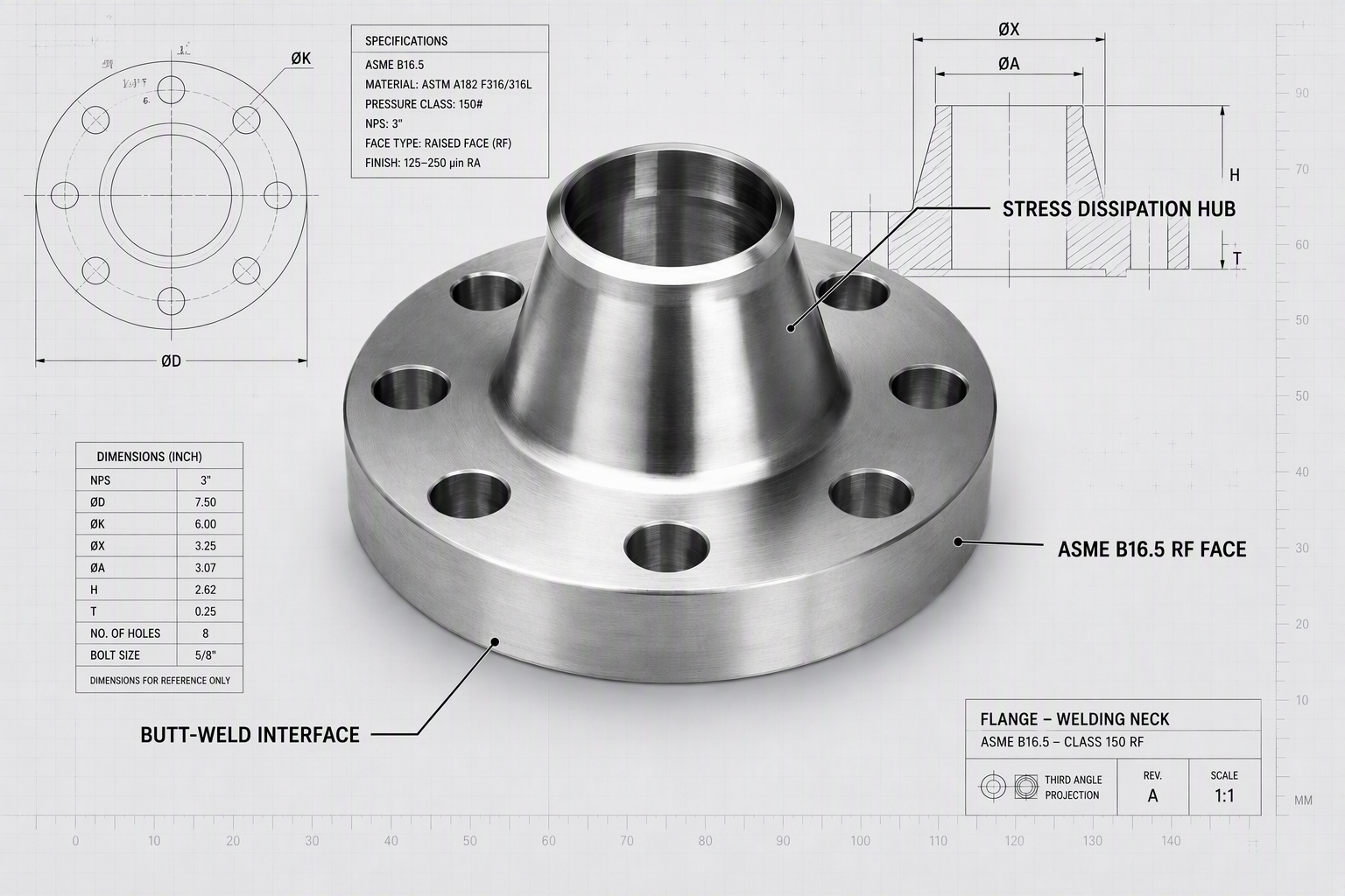
The fundamental distinction between a Weld Neck Flange and a standard Slip-on (SO) flange lies in the prominent tapered hub. From a mechanical perspective, this neck is not merely for welding convenience but serves as a high-precision model for stress attenuation.
1. Smoothing the Stress Concentration Factor (SCF): During high-pressure fluctuations, stress often surges at cross-sectional transitions. The tapered hub of the WNF acts as a mechanical ‘transition zone,’ utilizing its geometry to smooth and transfer localized stress from the flange base to the pipe body proportionally. Finite Element Analysis (FEA) indicates that under identical pressure pulses, the peak stress at a WNF joint is reduced by over 45% compared to slip-on connections.
2. Fatigue Cycle Endurance: Operational piping inevitably faces thermal expansion and fluid impact, requiring joints to endure tens of thousands of alternating load cycles. The butt-weld structure of the WNF eliminates the risk of ‘fillet weld fatigue cracking’ common in slip-on roots, significantly extending the system’s theoretical lifecycle.
|
Physical Metric |
Weld Neck (WNF) |
Slip-on (SO) |
Blind Flange (BL) |
|
Stress Transfer Efficiency |
Extreme (Tapered) |
Low (Fillet Weld) |
N/A (End Cap) |
|
Fatigue Cycle Limit |
> 50,000 Cycles |
< 15,000 Cycles |
N/A |
|
Vibration/Impact Resistance |
Excellent |
Moderate (Root Risk) |
High (Structural) |
|
Recommended Application |
Extreme HP/Cryogenic |
Mid-Low Pressure |
Maintenance Access |
II. Metallurgical Integrity: Physical Response and Mitigation in Extreme Environments
The reliability of stainless steel flanges depends not only on the grade (e.g., 304 or 316L) but also on the stability of the metallurgical microstructure at the microscopic level. Especially in chlorine-rich marine atmospheres or semiconductor chemical delivery, failure paths are often hidden.
1. Intergranular Corrosion and the ‘Chromium Carbide’ Trap: During welding, if the heat-affected zone (HAZ) of the tapered hub remains at critical temperatures too long, chromium combines with carbon to form chromium carbides along grain boundaries, leading to ‘chromium-depleted zones.’ This is a primary culprit for catastrophic brittle fracture. Technical certainty requires the mandatory use of ultra-low carbon grades (e.g., 316L) combined with rigorous Solution Annealing to reconstruct a uniform austenitic structure.
2. The Engineering Significance of PREN Values: Pitting Resistance Equivalent Number (PREN = Cr + 3.3Mo + 16N) is a hard engineering metric. For deep-sea applications, PREN must be locked above 35 to ensure the self-healing capacity of the surface passivation film after micro-damage.
|
Stainless Grade |
Temp. Range (℃) |
Typical PREN |
Key Physical Advantage |
|
ASTM A182 F304 |
-196 to 425 |
18 – 20 |
Cryogenic Toughness |
|
ASTM A182 F316L |
-196 to 450 |
24 – 26 |
Anti-pitting & Low Mag. |
|
ASTM A182 F310S |
-20 to 1100 |
28+ |
High-temp Oxidation Res. |
|
Duplex 2205 |
-50 to 300 |
34 – 36 |
2x Yield of Austenitic |
III. Sealing Surface Engineering: The Mechanical Interlocking of Ra Values
Even with perfect structure and metallurgy, the microscopic quality of the sealing surface determines the initial seal integrity. Under ASME standards, the Raised Face (RF) roughness is not ‘the smoother, the better.’
The standard Ra 3.2 to 6.3 μm serrated finish (Phonographic Finish) is designed to allow the peaks of the texture to locally embed into the gasket under bolting load. This microscopic ‘mechanical anchoring’ prevents ‘radial penetration’ of high-pressure media during pressure surges. If the surface is too smooth, the gasket may undergo lateral slippage under high-temperature creep, leading to catastrophic blowout.
|
Temp. (℃) |
Class 150 (bar) |
Class 300 (bar) |
Class 600 (bar) |
|
38 ℃ (Ambient) |
19.0 |
49.6 |
99.3 |
|
200 ℃ |
13.8 |
41.0 |
82.1 |
|
400 ℃ |
6.5 |
34.5 |
69.0 |
|
450 ℃ |
4.6 |
33.5 |
67.0 |
Note: Data based on ASTM A182 F316L. Engineering selection must strictly apply derating based on actual temperature rise, the first line of defense for system integrity.
IV. Failure Physics: Deconstructing Typical Risk Chains in WNF Joints
Based on Failure Mode and Effects Analysis (FMEA), flange failure is rarely a random accident but a consequence of exceeding physical boundaries during installation or maintenance. We have quantified key risks via RPN scores:
|
Failure Mode Item |
S (Severity) |
O (Occur.) |
D (Detect.) |
Total RPN |
|
Welding Root Misalignment |
9 |
4 |
6 |
216 (High Risk) |
|
Non-uniform Bolt Torque |
8 |
6 |
5 |
240 (High Risk) |
|
Gasket Surface Scratches |
7 |
3 |
9 |
189 (Med Risk) |
|
Stress Relaxation (Creep) |
8 |
5 |
4 |
160 (Med Risk) |
RPN quantification reveals that ‘Bolt Torque Management’ and ‘Welding Integrity’ represent higher risks than the material itself in current engineering practice. This drives our push for digital installation records and end-to-end quality traceability.
V. Conclusion: Establishing Global Engineering Certainty
The evolution of the Weld Neck Flange (WNF) marks a transition from ‘experience-based connection’ to ‘certainty-based connectivity.’ By precisely controlling stress paths, selecting rigorous metallurgical structures, and absolute adherence to international standards, we are not just manufacturing a forging—we are building a physical asset firewall for complex computing, energy, and semiconductor systems. The industry must move toward deeper failure analysis to safeguard every microscopic interface.
Frequently Asked Questions (Stainless Steel WNF Optimization)
Q: Why is a Weld Neck Flange (WNF) preferred over a Slip-on (SO) flange for high-pressure systems?
A: A WNF features a tapered hub that smoothly transfers localized stress to the pipe body, reducing the stress concentration factor by over 45%. It also eliminates fillet weld fatigue, offering a fatigue cycle limit of > 50,000 cycles, compared to < 15,000 for slip-on flanges.
Q: What is the significance of the PREN value in Yokey’s stainless steel flanges?
A: The Pitting Resistance Equivalent Number (PREN) determines a material’s capacity to resist localized corrosion. For extreme environments like deep-sea energy, Yokey locks the PREN above 35 (e.g., Duplex 2205 at 34-36) to ensure the self-healing integrity of the passivation film.
Q: How does Yokey address intergranular corrosion during the welding of stainless flanges?
A: Yokey mitigates this risk by using ultra-low carbon grades (e.g., 316L) and implementing mandatory Solution Annealing to reconstruct a uniform austenitic structure, preventing the formation of chromium-depleted zones at grain boundaries.
Q: What surface finish is required for a secure WNF seal under ASME standards?
A: Yokey follows ASME standards recommending a serrated finish (Ra 3.2 to 6.3 μm). This “phonographic finish” creates a mechanical anchoring effect, allowing the texture to embed into the gasket and prevent radial penetration of high-pressure media.
Post time: Jul-31-2026