
Executive Summary
Liquid cooling hose-end sealing is not only a static leakage problem. A reliable connection must maintain fluid containment while preserving hose retention, fitting engagement, clamp load, pressure resistance, thermal movement tolerance, vibration resistance and long-term pull-off resistance. The connection is a coupled system: hose bore, wall thickness, hardness, reinforcement, barb geometry, insertion depth, clamp position, coolant exposure and mechanical loading all influence the result.
A barbed fitting retains a hose through elastic interference, radial contact pressure and axial mechanical engagement. A clamp can increase local compression and stabilize the hose over the retention zone, but it cannot correct an incompatible fitting diameter, insufficient insertion depth or a damaged hose surface. Seal performance and pull-off resistance are related, but they are not the same engineering metric.
Long-term risk develops when pressure pulses, thermal cycling, vibration, bending and hose creep gradually reduce contact conditions. Coolant exposure can also change dimensions, hardness and elastic recovery. Therefore, pressure-hold, pull-off, thermal-cycle, pressure-cycle, vibration and teardown evidence should be interpreted together rather than treated as interchangeable proof.
Barbed Fitting and Hose-End Sealing Mechanism
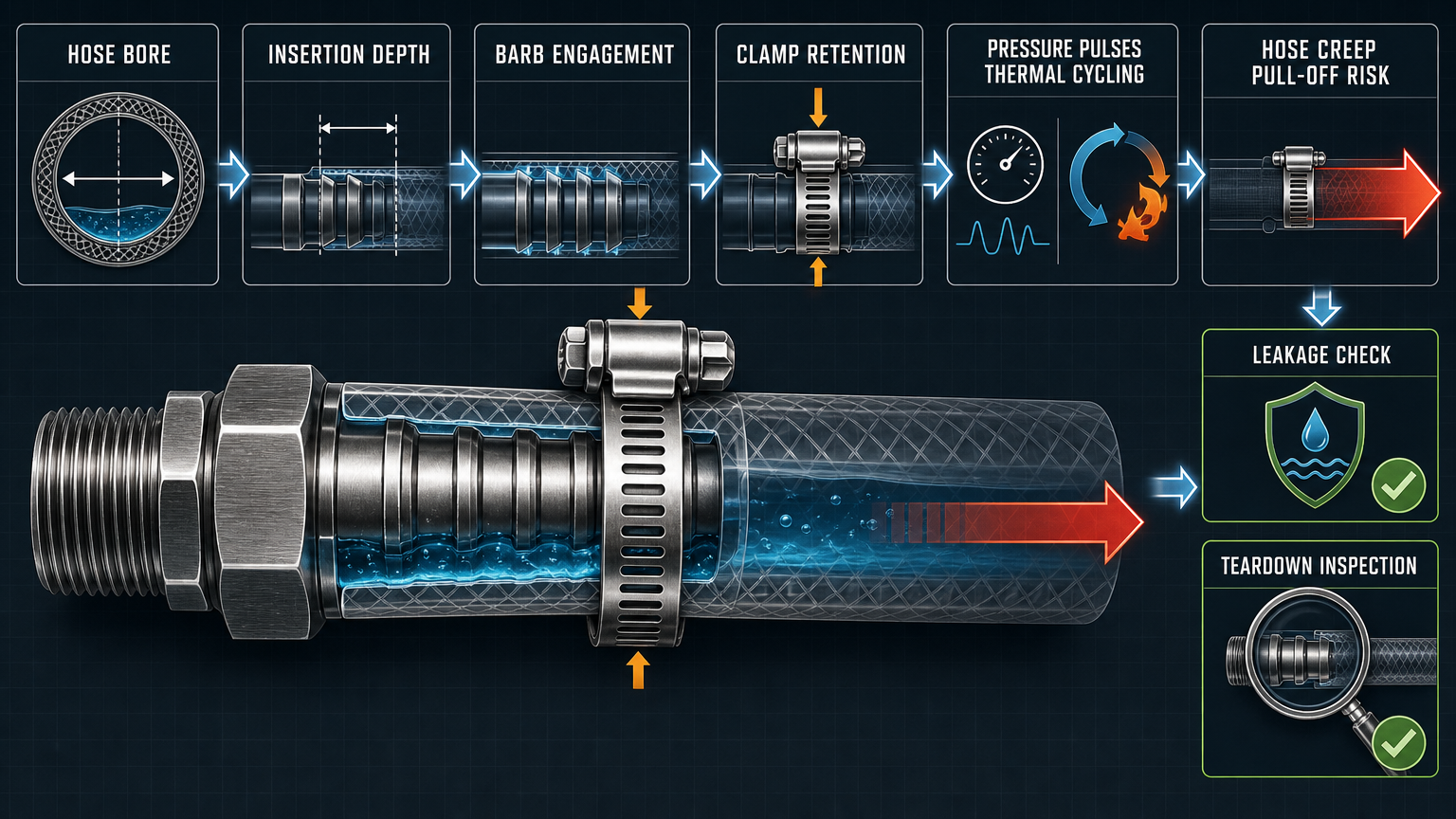
The hose-end connection begins with geometric compatibility. The fitting outside diameter must create controlled interference with the hose bore, while barb height, angle, spacing, nose radius and surface finish determine how the hose deforms during insertion and service. The hose wall stores elastic strain around the barb. Its recovery produces radial contact pressure, and the barb shoulder resists axial movement when an external load attempts to pull the hose away.
Insertion depth controls how many sealing and retention features are engaged. A shallow insertion can leave the hose supported only near its lip, creating a short contact zone and a high local stress concentration. Full engagement distributes deformation over the intended barb region, but excessive insertion force can damage the bore or reinforcement. The correct depth is therefore a design and assembly variable, not a visual assumption.
A clamp adds local radial compression. Its benefit depends on band width, stiffness, seating, position relative to the barb and the condition of the hose beneath it. The clamp improves contact pressure and may resist early slip, but it does not replace the mechanical contribution of the barb. A pressure boundary may remain tight while the hose is already moving axially, so leakage absence alone does not prove adequate retention.
Hose, Fitting and Clamp Compatibility
Hose, fitting and clamp selection must be evaluated as one assembly. Hose inner diameter, wall thickness, hardness, reinforcement layer and elastic recovery determine how the bore conforms to the fitting. Fitting outside diameter, barb height, barb spacing, edge radius and surface finish determine the deformation required. Clamp band width, edge condition and stiffness determine how compression is transferred into the hose. Assembly tolerance connects all three parts.
EPDM, silicone, FKM and PTFE-lined hose constructions can behave differently under the same assembly geometry. Differences in elastic recovery, creep, swelling, softening, hardening, permeation and compression-set tendency may alter both sealing contact and axial retention. These are application-dependent characteristics. The relevant question is whether the selected hose construction remains compatible with the fitting, clamp, coolant, temperature history, pressure range and movement condition.
A fitting that appears acceptable with one hose hardness or bore tolerance may be unsuitable with another. The assembly record should identify hose material and batch, measured bore and wall thickness, fitting geometry, clamp type and insertion depth. Substitution without rechecking these variables creates a design-control gap.
Table I: Hose-End Sealing and Retention Mechanisms
|
Mechanism |
Physical effect |
Typical stressor |
Failure symptom |
Recommended validation |
| Barb engagement | Shoulder resists axial movement | Pulling load or pressure pulse | Hose slip or partial pull-off | Axial pull-off test and movement mark |
| Elastic interference | Bore conforms to fitting surface | Bore tolerance or hardness change | Local leakage or low retention | Dimensional and hardness check |
| Insertion depth | Activates intended barb contact zone | Short insertion or assembly obstruction | Lip leakage and rapid slip | Visual depth mark and teardown |
| Clamp compression | Raises local radial contact pressure | Under- or over-tightening | Slip, cut or extrusion | Clamp audit and pull-off test |
| Surface condition | Controls friction and stress concentration | Scratch, burr or contamination | Bore damage or leak path | Surface inspection and teardown |
| Reinforcement response | Limits local expansion and movement | Layer damage or bend load | Crack, kink or end separation | Bend-load and post-test inspection |
This mechanism table separates the functions that are often incorrectly combined under the word “clamping.” The connection must first provide compatible barb engagement and hose contact; clamp compression then supports that geometry within its load and material limits.
Pressure, Temperature and Mechanical Load Effects
Internal pressure creates hoop expansion in the hose and can increase the axial tendency for the hose to move away from the fitting, especially when the geometry provides limited mechanical engagement. Pressure pulses add repeated loading rather than one static load. Their effect depends on amplitude, frequency, pressure differential, hose stiffness, fitting geometry and the restraint provided by adjacent components. A pressure-hold test captures containment at one condition; it does not reproduce repeated movement.
Thermal cycling changes hose dimensions and material response. A hose may soften, harden, contract, expand or lose elastic recovery depending on its construction, coolant and temperature history. The fitting and hose may also have different thermal movement. Repeated cycles can therefore change contact pressure and clamp load without an obvious external leak. Pump vibration, manifold misalignment, torsion, unsupported hose weight and bending at the fitting add local moments that can promote partial slip.
Mechanical relief should prevent the hose-end connection from carrying loads that belong to supports, guides or strain-control features. The assessment should include startup and shutdown, service access, adjacent component movement and the actual bend radius. These factors are part of retention design, not secondary installation details.
Table II: Temperature, Pressure and Assembly Influence Matrix
|
Stress factor |
Primary effect |
Secondary effect |
Potential failure mode |
Required measurement |
Main limitation |
| Static pressure | Hoop expansion and axial load | Contact pressure redistribution | Slip or leakage | Pressure and movement record | Single condition only |
| Pressure pulse | Repeated axial and radial loading | Fatigue and relaxation | Progressive slip | Cycle history and pull-off | Requires representative waveform |
| Thermal cycle | Dimension and modulus change | Clamp load variation | Thermal-cycle loosening | Temperature history and teardown | Does not isolate chemistry |
| Vibration | Micro-motion at joint | Friction loss and wear | Vibration-induced slip | Vibration and movement mark | Fixture may not match field |
| Bending or torsion | Local moment at fitting | Edge stress and notch growth | Cut, kink or partial pull-off | Bend-load test and visual check | Geometry-specific |
| Unsupported weight | Continuous axial and bending load | Creep acceleration | Long-term pull-off | Support audit and deflection | Depends on routing |
| Assembly tolerance | Changes interference and clamp seating | Uneven contact pressure | Leak or low retention | Bore, fitting and depth record | Needs controlled measurement |
The matrix is a load-screening tool rather than a universal qualification schedule. Test severity must be linked to the actual hose construction, fitting size, pressure history, temperature range, routing and support condition.
Clamp Load, Position and Installation Control
Clamp performance depends on where and how the band seats. The clamp should cover the intended retention region with uniform radial compression, without resting on a sharp barb edge or only on the unsupported hose lip. A shifted or tilted clamp can create an uneven pressure pattern: one side may be over-compressed while the opposite side remains weak. That condition can coexist with an initially acceptable pressure test.
Under-tightening may leave insufficient contact pressure and permit early movement. Over-tightening can cut or notch the hose, damage reinforcement, create local stress concentration or accelerate compression loss. The correct installation torque cannot be separated from clamp type, band width, hose structure, fitting diameter and tool condition. A fixed torque value should therefore not be transferred between assemblies without verification.
Installation control should include insertion-depth inspection, clamp-position inspection, visual confirmation of seating, controlled tooling where specified, post-assembly movement marks and recorded assembly information. Reusable clamps require particular attention because prior deformation, corrosion, thread condition or loss of spring response may change the applied load.
Coolant Compatibility and Long-Term Material Change
Coolant exposure can change the hose-end interface even when the fitting and clamp remain dimensionally unchanged. Swelling can reduce clearance or alter the stress distribution. Softening can reduce retention under pressure and vibration. Hardening can reduce conformability and increase crack sensitivity. Additive extraction, surface tackiness, permeation, particle shedding and dimensional change can also affect the contact zone.
Compatibility must be considered with temperature, duration, pressure, hose construction, reinforcement, fitting material and clamp geometry. A material coupon or immersion result can provide evidence for a defined fluid and temperature condition, but it does not automatically establish the pull-off life of a complete hose-end assembly. Post-exposure dimensional inspection, hardness comparison, pull-off testing and teardown are needed when long-term retention is the concern.
The maintenance record should identify coolant condition and any topping-up, cleaning or fluid change that could alter the hose. A hose that remains leak-free after immersion may still show reduced elastic recovery or increased creep. Conversely, a dimensional change does not prove imminent pull-off without load and assembly evidence.
Inspection, Testing and Maintenance
Verification should begin with assembly inspection. Record hose insertion depth, clamp position, hose and fitting dimensions, clamp type and any movement mark. A pressure-hold test evaluates pressure boundary and leakage at a defined condition. A pull-off or axial-load test evaluates retention directly. Pressure-cycle and thermal-cycle tests investigate whether contact and clamp conditions change under repeated service loading. Vibration and bend-load tests are useful when routing or equipment movement can load the joint.
Post-test teardown is essential for distinguishing mechanisms. Hose slip leaves an axial witness mark; a partial pull-off may show polished or displaced contact zones; a clamp cut or barb-induced notch may appear beneath the band; chemical swelling or hardening may be visible through dimensional and hardness changes. These observations should be recorded with pressure, temperature, cycle count, coolant condition, pull-off force and leakage result.
After hose replacement or reassembly, repeat the applicable inspection and pressure verification, then confirm insertion depth, clamp seating and movement marking. The required sequence depends on the system and maintenance boundary. No single pressure, time or torque value should be treated as a universal acceptance criterion.
Table III: Hose, Barb and Clamp Verification Guide
|
Test or inspection |
Test purpose |
Key variable |
Detectable failure |
Suitable stage |
Main limitation |
| Insertion-depth inspection | Confirm barb engagement | Depth mark and bore condition | Insufficient insertion | Assembly and service | Visual access may be limited |
| Clamp-position inspection | Confirm compression over retention zone | Band location and seating | Shifted or tilted clamp | Assembly and maintenance | Does not prove load |
| Pressure-hold test | Check pressure boundary | Pressure, time and temperature | External leakage | Commissioning and service | Does not prove pull-off life |
| Pressure-cycle test | Observe repeated pressure loading | Amplitude, frequency and cycles | Progressive slip or fatigue | Qualification | Needs representative waveform |
| Thermal-cycle test | Assess contact change with temperature | Range, ramp and dwell | Loosening or leakage | Qualification and audit | Chemistry may be uncoupled |
| Pull-off test | Measure axial retention | Force, speed and failure mode | Slip or complete pull-off | Design and validation | Fixture-specific result |
| Vibration or bend test | Assess mechanical routing loads | Frequency, amplitude or moment | Movement, cut or kink | System integration | Depends on support layout |
| Coolant immersion test | Observe material change | Fluid, temperature and duration | Swelling, hardening or softening | Material screening | Not a complete assembly test |
| Post-test teardown | Identify local damage | Marks, cuts, deformation and deposits | Barb damage or clamp injury | After every qualification | Destructive and sample-based |
The verification guide separates containment, retention, environmental exposure and mechanical routing. A complete qualification plan should combine the methods that represent the intended failure paths rather than using the easiest test as a substitute for all others.
Data Interpretation and Maintenance Planning
Test data become useful when the assembly identity is preserved. Record hose material and batch, measured bore and wall thickness, fitting geometry and barb dimensions, clamp type and position, insertion depth, coolant condition, temperature history, pressure range, pressure pulses, vibration, bending, pull-off force, leakage result and teardown morphology. Without these links, a force value or leak observation cannot be transferred confidently to another assembly.
Maintenance planning may use calendar, cycle, condition or risk-based triggers. A movement mark can reveal gradual slip before an external leak develops. Condition-based inspection should combine visual position checks with trend information and targeted testing after a service event. Laboratory pull-off force is evidence for the tested configuration; it is not a direct conversion to field service years.
A maintenance record should also capture whether the hose was removed, whether the clamp was reused, whether the fitting surface was inspected, whether the hose end was cut back, and whether the coolant or routing changed. These details help distinguish a design weakness from an assembly-induced event.
FMEA Risk Analysis
The following rankings are illustrative engineering risk rankings, not field statistics or experimental results. They show how a local design, material or assembly condition can propagate to leakage, loss of axial retention or interruption of the cooling loop. Actual occurrence, severity and detection values must be established from the specific configuration and service history.
Table IV: Liquid Cooling Hose-End Sealing FMEA and Illustrative RPN Analysis
|
Failure mode |
Cause |
Local effect |
System effect |
Detection method |
RPN |
Corrective action |
| Insufficient hose insertion | Assembly obstruction or short cut | Limited barb contact | Low retention and leak risk | Depth inspection and pull-off | High | Set depth control and inspect |
| Incorrect fitting size | Wrong specification or substitution | Poor interference | Slip or leakage | Dimensional check | High | Control part identity and fit |
| Clamp outside retention zone | Position error or poor access | Weak compression | Partial slip | Position mark and visual check | High | Define seating location |
| Clamp undertightening | Tool or process variation | Low contact pressure | Early movement or leak | Torque/load record and pull-off | Medium | Control tool and process |
| Clamp overtightening | Excessive load or wrong band | Cut, notch or extrusion | Delayed leakage or pull-off | Visual and teardown | High | Set assembly boundary |
| Hose creep | Time, temperature and load | Contact pressure loss | Progressive slip | Movement mark and pull-off | High | Validate material and support |
| Chemical swelling | Coolant incompatibility | Bore and modulus change | Leak or retention loss | Immersion, dimension and hardness | High | Approve fluid-material pair |
| Hose hardening | Thermal or chemical aging | Reduced conformability | Leak path and crack risk | Hardness and teardown | Medium | Review exposure and replace |
| Pressure-pulse fatigue | Repeated pressure loading | Micro-movement and damage | Long-term pull-off | Cycle record and teardown | High | Qualify representative pulses |
| Excessive bending load | Poor routing or unsupported weight | Local moment and edge stress | Slip, kink or cut | Bend audit and movement mark | High | Add support and strain relief |
| Vibration-induced slip | Pump or equipment vibration | Friction loss at interface | Progressive movement | Vibration and axial mark | Medium | Control vibration and routing |
| Hose cut by clamp edge | Sharp edge or tilted band | Local notch | Delayed external leakage | Visual inspection and teardown | High | Use suitable clamp and seating |
| Fitting surface damage | Burr, scratch or contamination | Stress concentration | Leak or bore damage | Surface inspection | Medium | Finish and clean fitting |
| Reassembly without inspection | Reused damaged hose or clamp | Hidden local damage | Recurring leak or pull-off | Maintenance audit | High | Replace or inspect defined parts |
| External leakage after partial slip | Progressive movement or damaged bore | Seal path opens locally | Coolant loss and service interruption | Leak trend and movement mark | High | Stop, replace and re-verify |
The FMEA separates design, material, assembly and operating causes. This prevents every event from being reduced to clamp torque and helps select a corrective action that addresses the actual failure path.
Conclusion
Liquid cooling hose-end reliability begins with compatible geometry. Barb height, angle, spacing, radius and surface condition establish the mechanical engagement, while hose bore, wall thickness, hardness and elastic recovery establish contact pressure. The clamp supports this interface by applying controlled radial compression, but it cannot compensate for wrong sizing, inadequate insertion or damaged material.
Pressure pulses, thermal cycling, vibration, bending, torsion, unsupported weight and manifold movement can change long-term retention. Coolant exposure may alter dimensions, hardness, swelling, softening, hardening and elastic recovery. Reliable verification therefore combines pressure-hold, pull-off, pressure-cycle, thermal-cycle, vibration or bend testing, material exposure and post-test teardown. Assembly records and post-maintenance re-verification are essential because a connection can remain apparently leak-free while its pull-off margin is declining.
Engineering FAQ
Q:How does a barbed fitting retain a liquid cooling hose?
A:It uses controlled interference, elastic recovery and barb geometry to create radial contact and resist axial movement. Retention depends on fitting size, hose bore, insertion depth, material response and the actual load path.
Q:Why can a hose pass a pressure-hold test but still have pull-off risk?
A:A pressure-hold test checks containment at a defined condition. It may not reproduce axial load, pressure pulses, thermal movement, vibration, bending or creep that gradually reduce retention.
Q:How does clamp position affect hose-end sealing?
A:The clamp must compress the hose over the intended barb retention zone. A shifted or tilted clamp can leave the active region weak while over-compressing another area, causing slip, cuts or uneven sealing.
Q:How do temperature and coolant exposure change long-term retention?
A:They can change hose dimensions, hardness, swelling, softening, hardening and elastic recovery. The resulting retention change must be assessed for the specific hose, coolant, temperature history and fitting assembly.
Q:What tests are needed after replacing a liquid cooling hose?
A:At minimum, verify insertion depth, clamp position and visible condition, then perform the applicable pressure and leakage check. Pull-off, thermal-cycle, pressure-cycle or teardown checks may be needed when the service risk warrants them.
Q:How can hose slip be distinguished from external leakage?
A:Use a reference mark to detect axial movement and inspect the contact zone after removal. Leakage identifies fluid escape, while slip can occur before leakage and may leave a displaced mark, polished zone or altered clamp position.
Post time: Aug-27-2026