
Executive Summary
AI liquid cooling infrastructure must provide more than heat-removal capacity. It must continue operating through defined component failures and allow technicians to detect, isolate, replace, verify and restore a module without unnecessarily interrupting the compute load. A single pump, filter, valve, CDU module or control component can affect one server, one rack, a rack group, a CDU zone or the entire cooling loop, depending on its location and the availability of independent flow paths.
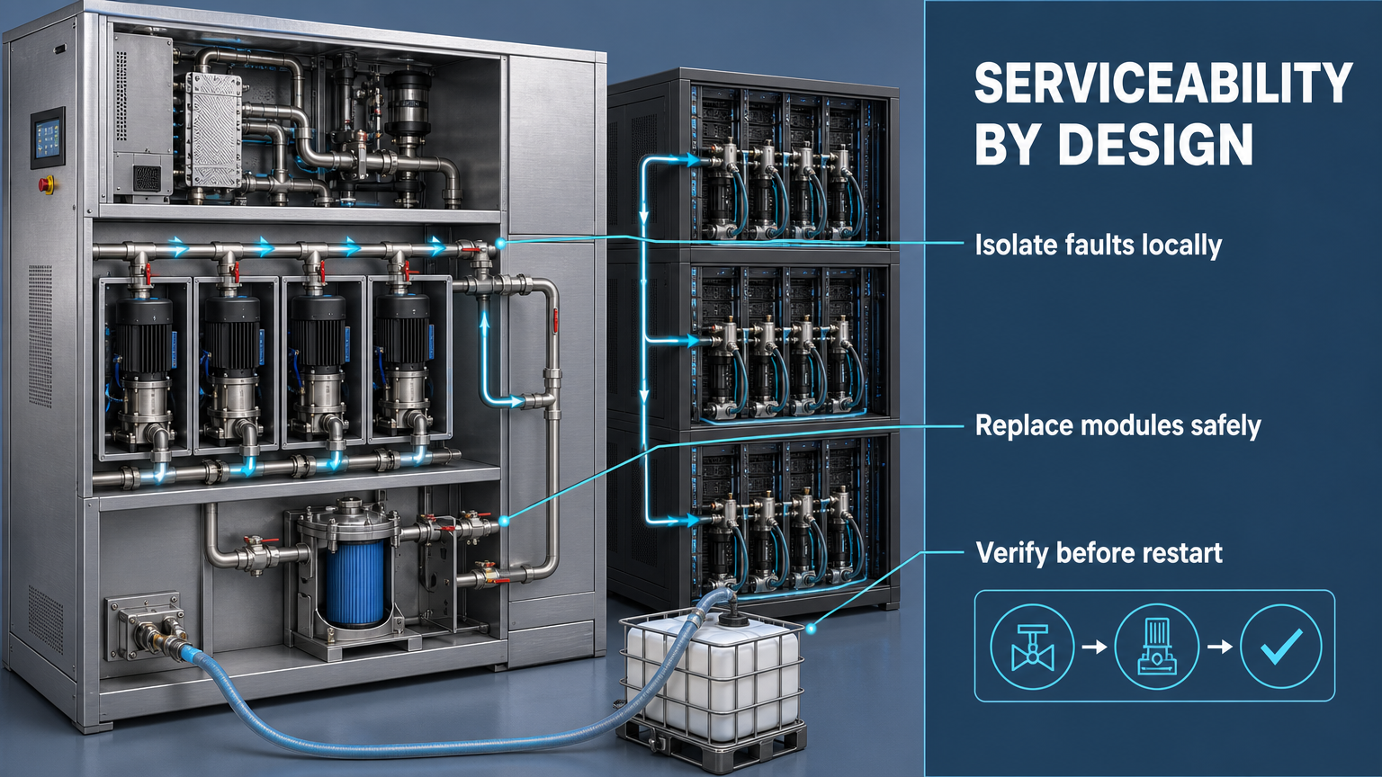
Serviceability by design means that redundancy, fault isolation and maintenance procedures are planned as one system. Installed redundancy is the hardware capacity that has been added. Available redundancy is the capacity that can actually take over after a fault. Maintenance redundancy is the capacity and protection margin that remain while one module is intentionally isolated. These states are not interchangeable.
A spare pump that shares the same power supply, controller, manifold or isolation path as the failed pump may not provide independent protection. Likewise, a modular architecture does not eliminate coolant loss, air ingress, particle contamination or downtime. It reduces exposure only when the complete sequence—normal operation, fault detection, isolation, replacement, verification and recovery—has been designed and tested.
Single-Point Failure Analysis in Liquid Cooling Systems
Single-point failure analysis identifies a component whose failure can interrupt a required cooling function because no independent path is available. The analysis should define the affected boundary first, then trace the consequence and the recovery path. A pump failure in one isolated CDU module is different from a failure in a shared pump train; a filter that can be bypassed is different from a filter installed in the only flow path.
The main candidates include the CDU pump, main distribution manifold, primary isolation valve, filter unit, control power supply, communication controller, rack-level quick-disconnect interface and reservoir or expansion component. Each should be reviewed for failure mode, affected scope, remaining cooling capacity, isolation possibility, common dependencies and maintenance access.
The failure categories should remain separate. A component failure affects one item; a localized failure is contained by a defined boundary; a common-cause failure affects primary and standby paths together; a maintenance-induced failure is introduced by an intervention; and a system-wide failure exceeds the intended zone boundary. The design target is not merely to add a spare, but to keep a fault from expanding beyond the smallest practical scope.
Table I: Single-Point Failure and Impact Scope Matrix
|
Component |
Failure mode |
Affected scope |
Cooling consequence |
Isolation possibility |
Recommended redundancy |
| CDU pump | Loss of flow or start failure | CDU zone to loop | Reduced or lost cooling capacity | Possible if pump and valves are independent | N+1 or active dual pump |
| Filter | Blockage or service removal | Rack group or CDU zone | Flow restriction or maintenance outage | Possible with bypass and isolation | Parallel serviceable filter path |
| Isolation valve | Fails open or closed | Local module to zone | Cannot isolate or maintain flow path | Depends on valve arrangement | Accessible independent isolation |
| Main manifold | Leak, blockage or structural fault | Multiple racks or zone | Shared distribution loss | Limited if common header | Segmented headers and bypass |
| Control power | Supply loss or transfer failure | CDU or complete control zone | Pumps and valves may not respond | Only if power domains are independent | Redundant power paths |
| Communication controller | Link or controller failure | CDU, rack group or zone | Loss of coordinated control | Possible with local fallback | Dual paths and safe local control |
The table is a boundary-analysis tool, not a universal failure-rate model. The actual affected scope must be established from the installed piping, power, controls, isolation points and heat-load envelope.
Redundant Architecture for CDU and Cooling Loops
N+1 pump redundancy provides one additional pump beyond the required operating set, but the label is meaningful only when the standby has adequate capacity and an independent changeover path. Active dual-pump operation can share capacity and expose failure quickly, while a standby pump reduces normal operating complexity but may hide start failure until it is demanded. Both arrangements require proof of power, control, valve state, flow response and alarm behavior.
Parallel CDU modules can reduce the blast radius of a module fault and support planned maintenance, but shared headers, power, heat rejection, controls or cooling-water sources can remain common-cause paths. A bypass loop can support filter or module service only if its capacity is sufficient for the actual load and its valves are accessible and verifiable. Segmented cooling zones reduce the affected boundary but add interfaces that require their own inspection and testing.
Automatic changeover is not automatically reliable. It depends on fault detection, control power, communication, actuator response and the ability of the remaining path to carry the heat load. Manual changeover depends on personnel response, operating procedure and maintenance-window control. The final design should be tested in normal operation, after one component failure and during planned maintenance.
Table II: Redundancy Architecture Comparison
|
Architecture |
Redundancy type |
Main benefit |
Main limitation |
Changeover method |
Common-cause risk |
Suitable application |
| N+1 pump | Standby or active | Retains required pump capacity after one failure | Spare may share power or controls | Automatic or manual | Shared suction, power or controller | CDU pump train |
| Dual-pump system | Active | Capacity sharing and immediate response | Both pumps can see same fault | Continuous operation | Shared manifold or coolant condition | High-duty CDU zone |
| Standby pump | Standby | Lower normal operating complexity | Start failure may remain hidden | Automatic or manual | Start command and power path | Low-load or service backup |
| Parallel CDU modules | Active or standby | Limits impact to a module or zone | More interfaces and controls | Automatic or planned | Shared headers, power or heat rejection | Segmented rack groups |
| Bypass loop | Path redundancy | Supports isolation and service | May have limited capacity | Manual or automatic | Shared valves and controls | Filter or module maintenance |
| Segmented cooling zones | Spatial redundancy | Reduces blast radius | Requires more distribution hardware | Zone-level | Common source or control layer | Large AI data halls |
A redundancy architecture must be evaluated in three states: normal operation, one defined failure and planned maintenance. Installed redundancy alone does not prove that the remaining path can support the actual heat load or that technicians can change the module without disturbing healthy equipment.
Modular Maintenance and Fault Isolation
Modular maintenance begins with a defined boundary. Accessible isolation valves, drain and fill points, venting points, pressure-equalization paths and coolant-recovery connections allow one rack, filter, pump or CDU module to be separated from the healthy loop. Service clearance and connector orientation are part of the reliability design because inaccessible components increase diagnosis time and create maintenance-induced risk.
A controlled intervention should identify the fault, reduce or transfer load if required, isolate the module, recover the coolant, equalize pressure, replace the compatible module, reconnect sensors and controls, remove air, perform pressure and leak checks, and conduct a controlled restart. Open connections should be capped and handled in a clean service area to limit particle entry. Coolant identity and recovered quantity should be recorded to prevent fluid mix-up.
The bypass path must be sized for the maintenance case rather than assumed to be adequate. After replacement, insulation, sensor connections, valve-position feedback and communication links must be restored. “Replacement complete” is not the same as “safe to return to service”; pressure, air removal, cleanliness, sensor validity and stable operation require explicit release conditions.
Table III: Modular Maintenance and Verification Checklist
|
Maintenance stage |
Required action |
Main risk |
Verification method |
Restart condition |
| Isolation | Close defined valves and confirm boundary | Wrong module or incomplete isolation | Valve state, pressure and flow check | Affected module separated |
| Coolant recovery | Recover and identify fluid in a controlled container | Loss, mix-up or contamination | Quantity and fluid record | Recovery complete and connections capped |
| Component replacement | Install compatible module with correct orientation | Wrong part, seal damage or misfit | Part and installation inspection | Module secured and connections correct |
| Air removal | Vent and prime the serviced path | Air pocket or unstable flow | Vent record, flow and temperature trend | Stable flow with no air indication |
| Particle control | Keep openings capped and service area clean | Particles enter the loop | Inspection and cleanliness record | Connection condition accepted |
| Pressure test | Apply defined pressure check to serviced boundary | Hileak or deformation | Pressure hold and inspection | |
| Sensor reconnection | Restore sensors, feedback and communications | Invalid control or alarm state | Signal plausibility and alarm test | All required signals valid |
| Controlled restart | Return module gradually under observation | Premature load or unstable state | Flow, temperature and alarm record | Stable operation documented |
Each maintenance action should have an observable release condition. A checklist improves serviceability only when the records show that isolation, coolant recovery, air removal, pressure testing, cleanliness, sensor validity and controlled operation were completed.
Availability, Maintenance Time and Verification
Mean Time Between Failures (MTBF) describes the average interval between failures within a defined population and system boundary. Mean Time To Repair (MTTR) includes fault detection, access, isolation, diagnosis, spare retrieval, replacement, reconnection, verification and restart—not only the time spent changing a component. Planned maintenance time and unplanned downtime should be recorded separately.
An illustrative engineering example can show the logic without claiming a universal result: reducing replacement time improves availability only when the fault is detected quickly, the spare is compatible, the module can be isolated and verification does not reveal a secondary fault. A short replacement action cannot compensate for long diagnosis, poor access or an unavailable spare.
Availability analysis should therefore include fault-detection time, isolation time, diagnosis time, spare availability, module replacement time, pressure and cleanliness verification, sensor reconnection and restart time. It should also account for common-cause failures that can remove both primary and standby paths.
FMEA Risk Analysis
Serviceability FMEA identifies failures that can turn a planned intervention or local component fault into a larger cooling outage. Required failure modes include single pump failure, standby pump failure to start, isolation-valve failure, insufficient bypass capacity, air introduced during filter replacement, particle contamination, incorrect module installation, spare incompatibility, communication failure, common power failure, premature restart and insufficient maintenance access.
FMEA must separate component failure, maintenance-induced failure and common-cause failure. RPN is a prioritization aid, not a universal safety limit. The rankings below are illustrative engineering assessments, not certification results or field-failure statistics. Project values require documented Severity, Occurrence and Detection scales and the project-required Action Priority method where applicable.
Table IV: Serviceability FMEA and RPN Analysis
|
Failure mode |
Cause |
Local effect |
System effect |
Detection method |
Illustrative RPN |
Corrective action |
| Pump replacement failure | Wrong module or incomplete reconnection | No stable flow | Cooling capacity loss | Installation, flow and alarm check | 170 | Compatible spare and restart checklist |
| Valve isolation failure | Valve inaccessible, wrong state or failed actuator | Module remains connected | Large maintenance exposure | Pressure and valve-position check | 165 | Independent isolation proof |
| Air ingress | Poor venting or pressure equalization | Unstable local flow | Cooling degradation or noise | Vent record and flow trend | 155 | Controlled fill, vent and prime |
| Particle contamination | Open connection or poor service control | Restriction or wear risk | Long-term reliability loss | Inspection and cleanliness record | 180 | Capping and clean-service procedure |
| Incorrect module installation | Orientation or connection error | Local control or flow error | Zone outage or unsafe state | Part and functional inspection | 175 | Keyed interfaces and verification |
| Spare incompatibility | Revision, connector or fluid mismatch | Cannot restore module | Extended downtime | Part-number and fit check | 160 | Controlled spare inventory |
| Communication failure | Link loss or wrong configuration | No coordinated control | Fault isolation or restart failure | Communication and alarm test | 150 | Local fallback and dual path |
| Premature restart | Drying, pressure or cleanliness check skipped | Unverified module enters service | Repeat failure or wider outage | Restart gate and record review | 190 | Formal release criteria |
All RPN values in this table are illustrative engineering assessments. They are not universal safety limits, certification results or field-failure statistics. High-priority actions should become design requirements, maintenance steps, alarm tests, spare-part controls and restart gates.
Conclusion
A reliable AI liquid cooling system should not be designed only for heat-removal capacity. It must also be detectable, isolatable, replaceable, verifiable and recoverable. Redundancy protects capacity only when the remaining path has independent power, control, isolation and proven changeover capability.
Serviceability is established during design through segmented zones, accessible valves, bypass paths, coolant recovery, venting, clean connections, compatible spares, sensor reconnection and controlled restart procedures. FMEA and availability analysis should evaluate normal operation, local failure, maintenance and recovery as separate states. No modular architecture eliminates downtime or contamination risk by itself; it reduces exposure when the system is designed and verified as a complete maintenance process.
Engineering FAQ
Q:What is the difference between N+1 redundancy and true fault isolation?
A:N+1 provides additional capacity after a defined component failure. Fault isolation limits the physical and hydraulic effect of that failure to a defined boundary. A system can have N+1 pumps and still lack true isolation if the pumps share one power source, controller, manifold or valve path.
Q:How can a CDU pump be replaced without shutting down the entire cooling loop?
A:The architecture must provide an independent pump path, accessible isolation valves, adequate bypass or remaining capacity, controlled coolant recovery, venting and a verified changeover sequence. The actual method must be proven under the required heat-load condition.
Q:What risks are introduced during coolant recovery and module replacement?
A:The main risks are coolant loss, fluid mix-up, air ingress, particle contamination, wrong-part installation, damaged connections and incomplete sensor restoration. Recovery containers, capped openings, clean procedures and a documented restart gate reduce these risks.
Q:How should a liquid cooling system be verified after maintenance?
A:Verify module identity and orientation, pressure-boundary condition, flow, temperature, air removal, cleanliness controls, sensor validity, alarms, valve state and stable operation under a controlled restart. Record the result before returning the module to normal service.
Q:Why can redundant systems still fail from a common-cause event?
A:Primary and standby components may share power, control logic, manifolds, coolant condition, environmental exposure or maintenance errors. A common-cause review must identify shared dependencies and test the independence of the remaining path.
Q:Which maintenance parameters should be recorded for long-term reliability analysis?
A:Record fault detection time, isolation time, diagnosis time, spare retrieval time, replacement time, coolant recovered, pressure-test result, air-removal result, restart time, alarm status, technician actions and any repeat fault.
Post time: Aug-19-2026